
Data loggers
IM80
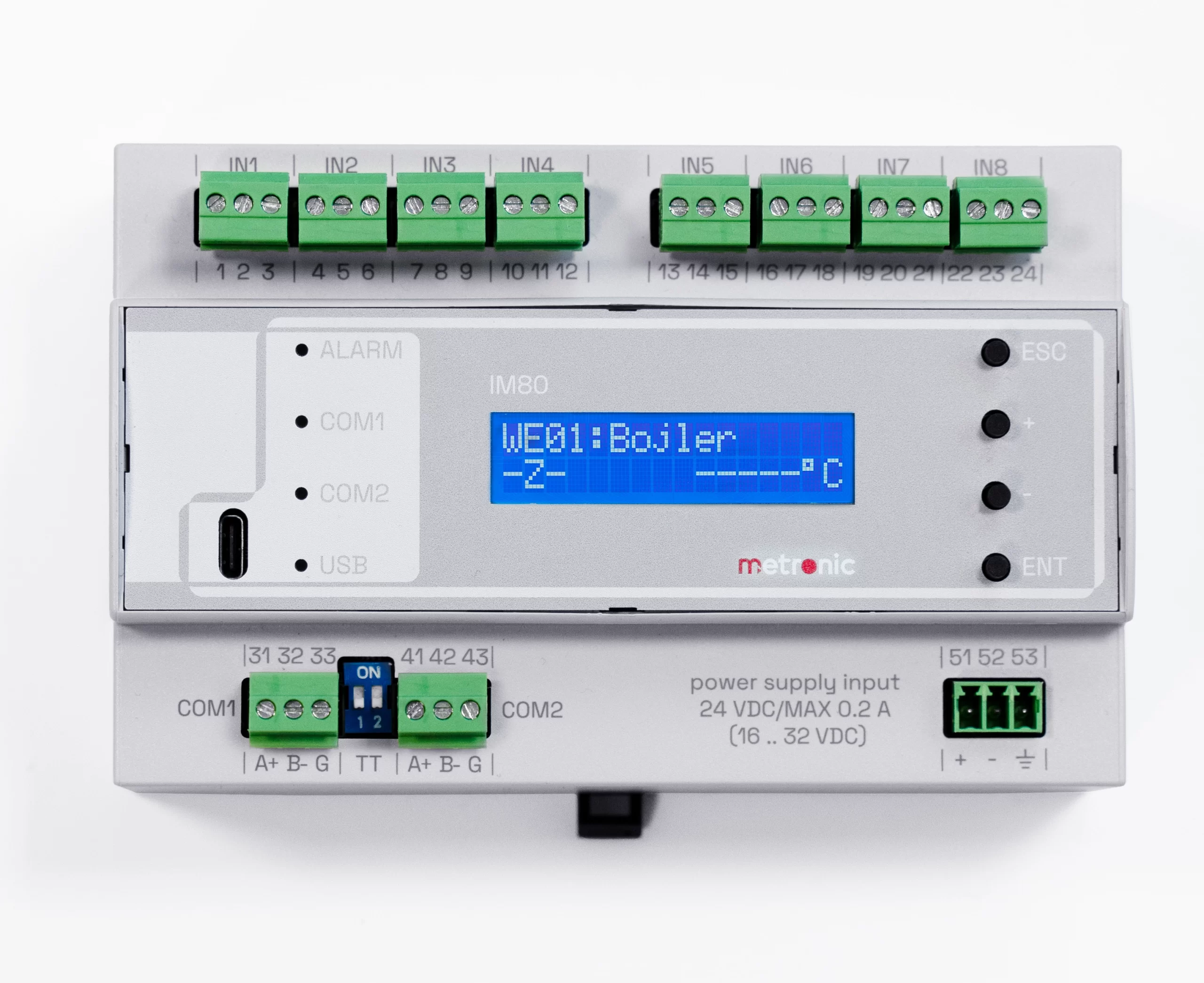
The IM80 is a precision programmable analog input module designed for use in a distributed measurement or control system. Eight measurement channels allow the connection of RTDs, TC thermocouples, or 4-20mA current signals. The input signals are processed in an 18-bit A/D converter. The data received from the transmitter is digitally linearized and processed by the microprocessor system, and then made available to the master system via the COM1 (RS-485 / Modbus RTU) SLAVE communication port. The second COM2 (RS-485 / Modbus RTU) MASTER communication port allows you to connect additional IM80 modules to increase the number of measurement channels.
The device is designed to measure and recording process signals in industrial installations and can be used to measure physical quantities converted into a standard signal, such as: temperature, humidity, pressure, flow, level, chemical composition, etc.
8 Channel Analog Input Module
- 8 analog inputs RTD / TC / I / U / R
- 72 measurement channels
- Display LCD 2×16 characters
- Port USB C on the front panel
- Port RS–485, Modbus RTU Master
- Port RS–485, Modbus RTU Slave
- Internal memory recording
- Configuration software
- Dimensions 90.5 x 142.5 x 62 mm
- Power 24VDC (16-32VDC)
Basic functions
- Measurement of process variables in 8 channels
- Sensor measurement Pt100, Pt1000, Ni100, Cu50, Cu53, KTY-81
- Thermocouple measurement B, E, J, K, L, N, R, S, T, U
- Resistance measurement 0..400 Ω, 0..4000 Ω
- Voltage measurement -0,2..+0,2 V, -1,3..+1,3 V
- Current measurement 0..20mA / 4..20mA
- Remote readout in 64 channels
- Recording in 2GB memory
- Communication with the superior computer system
- Reading parameters from modules in the local network
| Front panel | |
| Display Type | LCD alphanumeric
2 x16 characters with backlight |
| Character height | 4,5 mm |
| LEDs | 4 tricolour (ALARM, COM1, COM2, USB) |
| Keyboard | 4 push buttons |
| Port USB | USB-C |
| Terminal blocks | |
| Input signals | 8 screw three-terminal connectors 1,5mm2 |
| Communication Ports COM1, COM2 | 2 screw three-terminal connectors 1,5mm2 |
| Port COM1 RS-485 – SLAVE | |
| Signals output on the connector | A(+), B(-), G, G (G – signal ground) |
| Load | 256 receivers/transmitters |
| Transmission Protocol | Modbus RTU Slave |
| Baud | 9.6, 19.2, 38.4, 57.6, 115.2 kbps |
| Parity check | Even, Odd, None |
| Frame | 1 start bit, 8 data bits, 1 stop bit |
| Galvanic isolation | 250 VAC; 1500 VAC for 1 min |
| Maximum Line Length | 1200 m |
| Bus termination | Vcc-A(+)-B(-)-G: 390 Ω – 220 Ω – 390 Ω – DIP SW |
| Maximum differential voltage A(+), B(-) | -7 V .. +12 V |
| Minimum transmitter output | 1,5 V (at RL= 54 W) |
| Minimum receiver sensitivity | 200 mV / RIN= 12 kW |
| Minimum data line impedance | 54 W |
| Short circuit/thermal protection | Yes/Yes |
| Port COM2 RS-485 – MASTER | |
| Signals output on the connector | A(+), B(-), G, G (G – signal ground) |
| Load | 256 receivers/transmitters |
| Transmission Protocol | Modbus RTU Master |
| Baud | 9.6, 19.2, 38.4, 57.6, 115.2 kbps |
| Parity check | Even, Odd, None |
| Frame | 1 start bit, 8 data bits, 1 stop bit |
| Galvanic isolation | 250 VAC; 1500 VAC for 1 min |
| Maximum Line Length | 1200 m |
| Bus termination | Vcc-A(+)-B(-)-G: 390 Ω – 220 Ω – 390 Ω – DIP SW |
| Maximum differential voltage A(+), B(-) | -7 V .. +12 V |
| Minimum transmitter output | 1,5 V (at RL= 54 W) |
| Minimum receiver sensitivity | 200 mV / RIN= 12 kW |
| Minimum data line impedance | 54 W |
| Short circuit/thermal protection | Yes/Yes |
| Power Supply | |
| Supply voltage | 24 VDC (16 .. 32 VDC) |
| Maximum power consumption | 1.5W typically , 4.8W max. |
| Connecting the wires (screw connectors) | |
| Type | Detachable screw connectors |
| Wire cross-section | Cable and strand 0.14 .. 1.5 mm2 |
| Working conditions | |
| Operating Temperature | 0 °C .. +50 °C |
| Humidity | 5 .. 90% (non-condensing) |
| Storage Temperature | -10 °C .. +70 °C |
| Mechanical dimensions | |
| Enclosure type | For mounting on the TS-35 or wall |
| Dimensions (height x width x depth) | 90.5 x 142.5 x 62 mm (64.5 mm with terminals) |
| Mass | ok. 0.3 kg |
| Protection | IP30 |
| Analog inputs | |
| Number of inputs | 8 (we1 .. we8) |
| Galvanic separation between channels | No |
| Galvanic separation from the supply voltage | 250 VAC; 1500 VAC for 1 min |
| Maximum input voltage | +/-30VDC or 30Vp-p between the terminals ABC |
| RTD inputs | |
| Measuring range | 0..4000 Ω |
| Sensor Type | Pt100, Pt1000, Ni100, Cu50, Cu53, KTY-81 |
| Sensor current | 250 µA |
| Sensor connection | 3-wire or 2-wire |
| 2p wire resistance compensation | A fixed adjustment in the range of –10 Ω do 10 Ω |
| TC Inputs | |
| Measuring range | -140 .. +140mV |
| Sensor Type | B, E, J, K, L, N, R, S, T, U |
| Cold junction compensation | Fixed, Internal, External |
| Cold junction compensation range | -50.0 °C do +100.0 °C |
| Maximum Conductor Resistance | 2 x 300 W |
| Measurement accuracy | According to the table for the sensor type |
| R inputs | |
| Measuring range | 0 .. 400 W
0 .. 4000 W |
| Processing characteristics | Linear |
| Sensor connection | 3-wire or 2-wire |
| Measurement accuracy (Ta=25°C) | <±0.5 Ω (0..400 W)
<±1.0 Ω (0..3000 W) <±8.0 Ω (3000..4000 W) |
| Inputs I | |
| Measuring range | 0 .. 20mA
4 .. 20 mA |
| Processing characteristics | Linear |
| Sensor connection method | 2-wire with external power supply |
| Basic error (Ta=+25°C) | <±0,1 % of measurement range |
| U inputs | |
| Measuring range | -0.2 .. +0.2 V
-1.3 .. +1.3 V |
| Processing characteristics | Linear |
| Sensor connection method | 2-wire |
| Measurement accuracy (Ta=25°C) | <±0.1% of measurement range |
| Remote inputs | |
| Number of inputs | 64 (WE9 .. WE72)
Read via COM2 port Modbus protocol RTU |
| Range of supported registers | 30000 .. 39999, 300000 .. 365535 40000 .. 49999, 400000 .. 465535 |
| Supported number format | uint(16b), int(16b), uint(32b), uint(32b)sw, int(32b), int(32b)sw, float(32b), float(32b)sw, int(64b), double(64b) |