
Flow computers
FP40
FP40 is versatile and precise flow computer used for measurement of steam and water in various industrial installations, measurements of industrial gases and typical or special liquids (like glycol, supercooled water, oils) in heat exchange systems. There is possibility of local alarming or simple control implementation. Data are recorded and can be read locally or periodically using a USB mass storage device.
Device can communicate with master system via Ethernet port (Modbus TCP protocol, www server) or via RS-485 port (Modbus RTU protocol) and can work in distributed control systems.
Device may be configured by the user from the front panel or using commissioning software on PC.

Flow computer for calculating compensated flow and thermal energy of steam, water and other liquid media
- Modular design of inputs and outputs
- Billing of 1 or 2 different measuring applications
- Auxiliary measurements and calculations
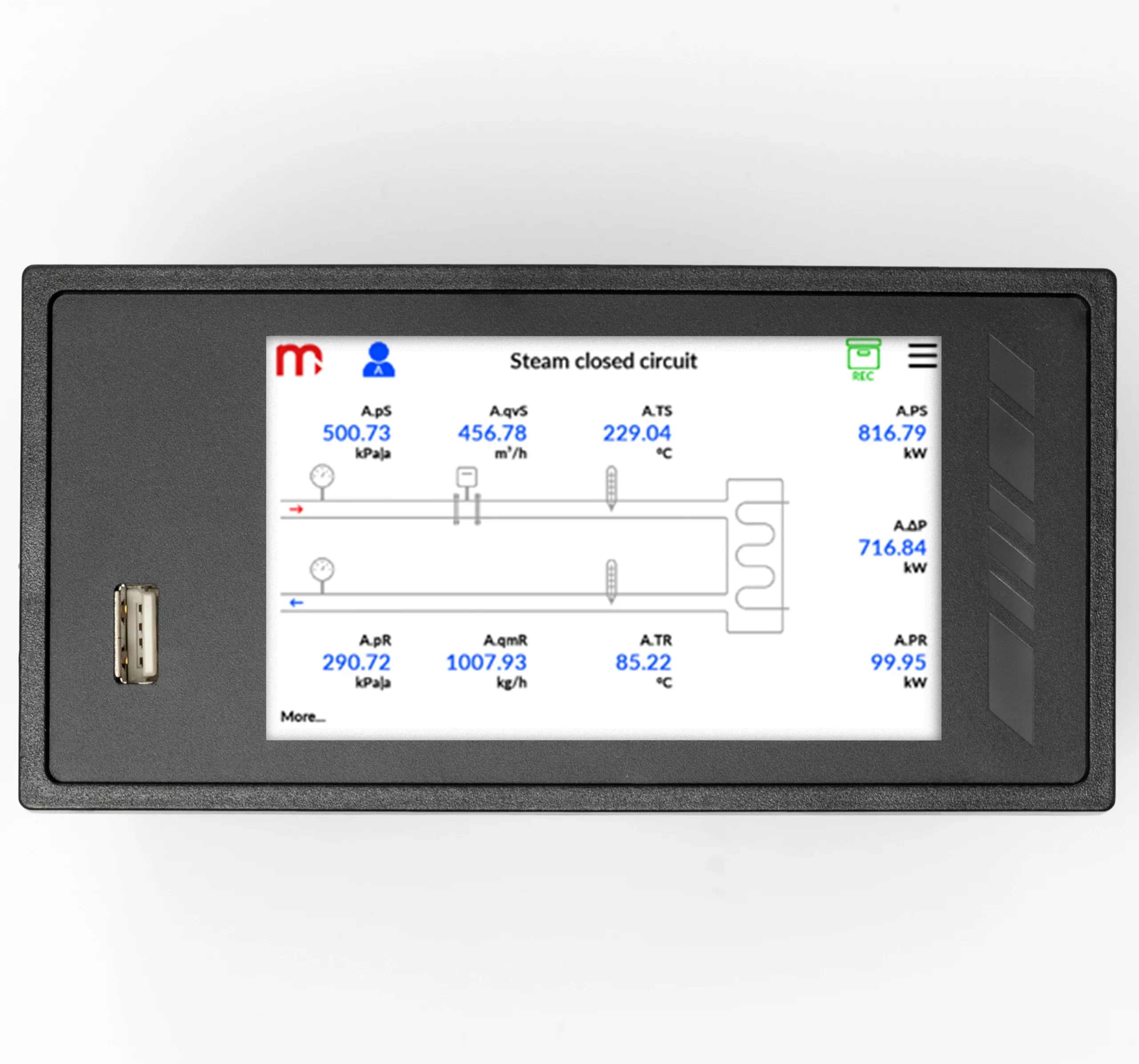
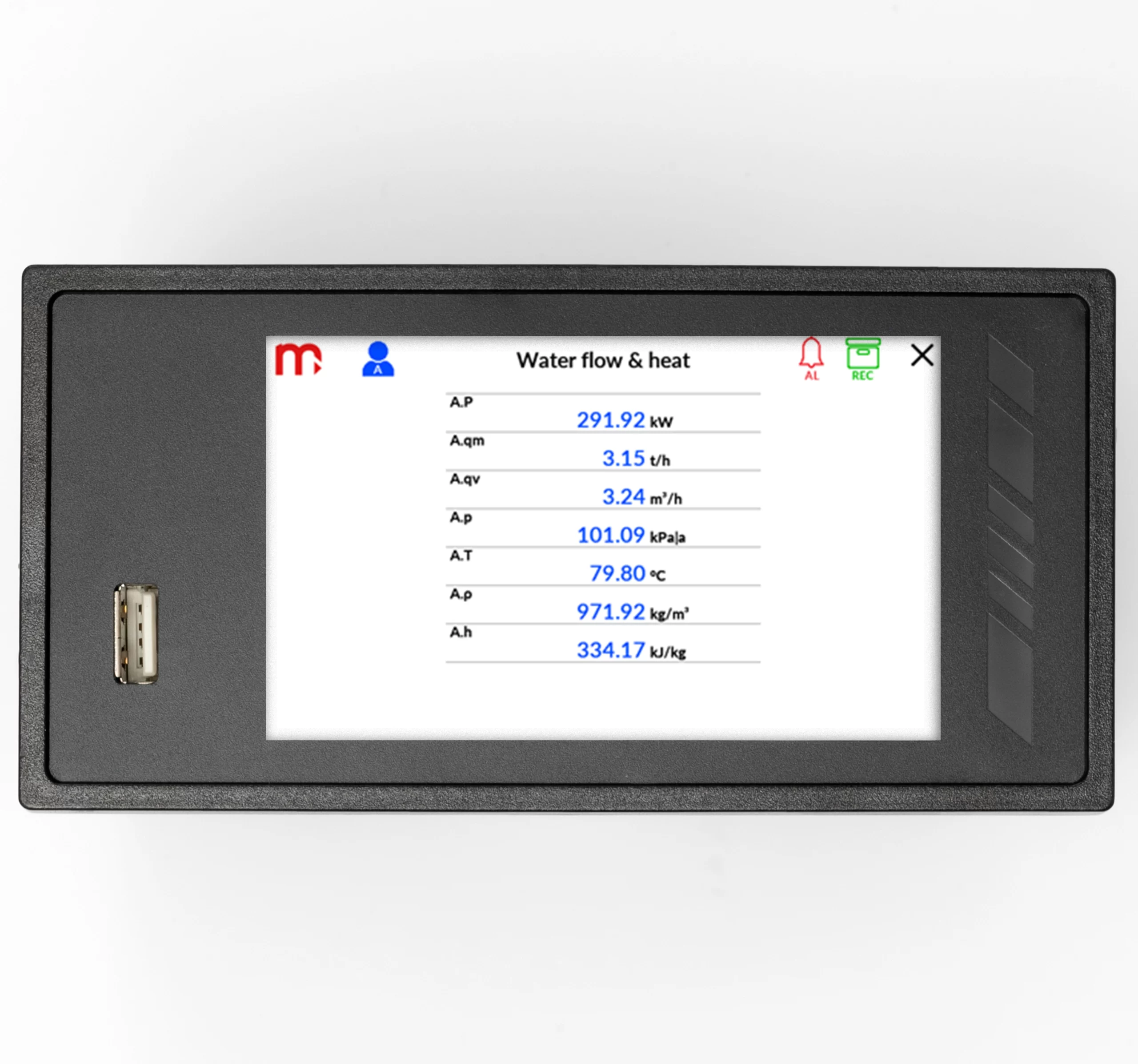
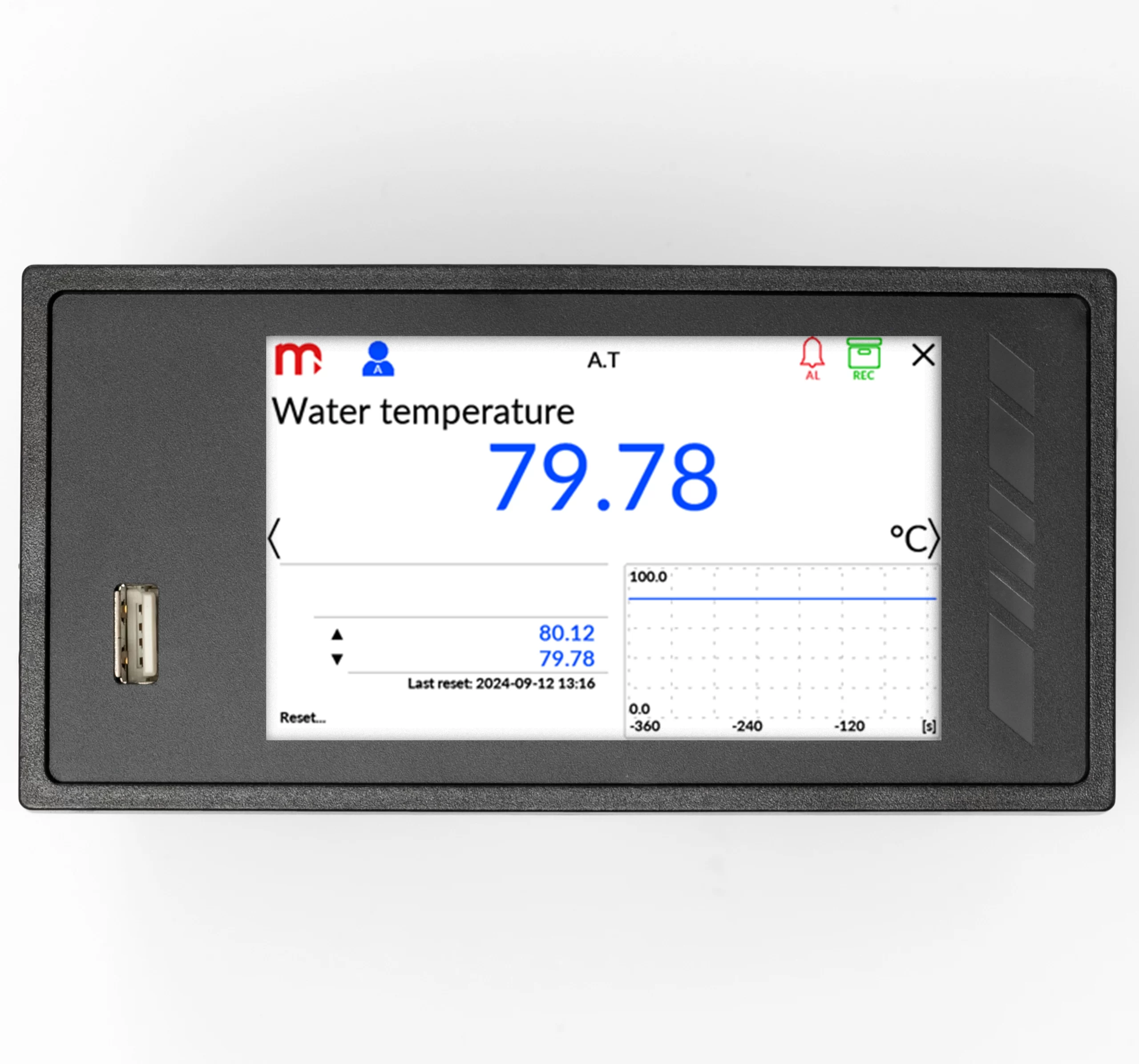
- Touchscreen 4″ colour LCD display
- Graphical diagram of the measuring application
- Math channels, functions +, -, /, *, √, ^
- Alarm and control functions
- 4 output relays (6 more optional)
- 1 analog output 4-20mA (3 more optional)
- Port Ethernet, Modbus TCP Client/Server
- Port RS–485, Modbus RTU Master/Slave
- USB port on the front panel
- Email message on alarms status and totalisers
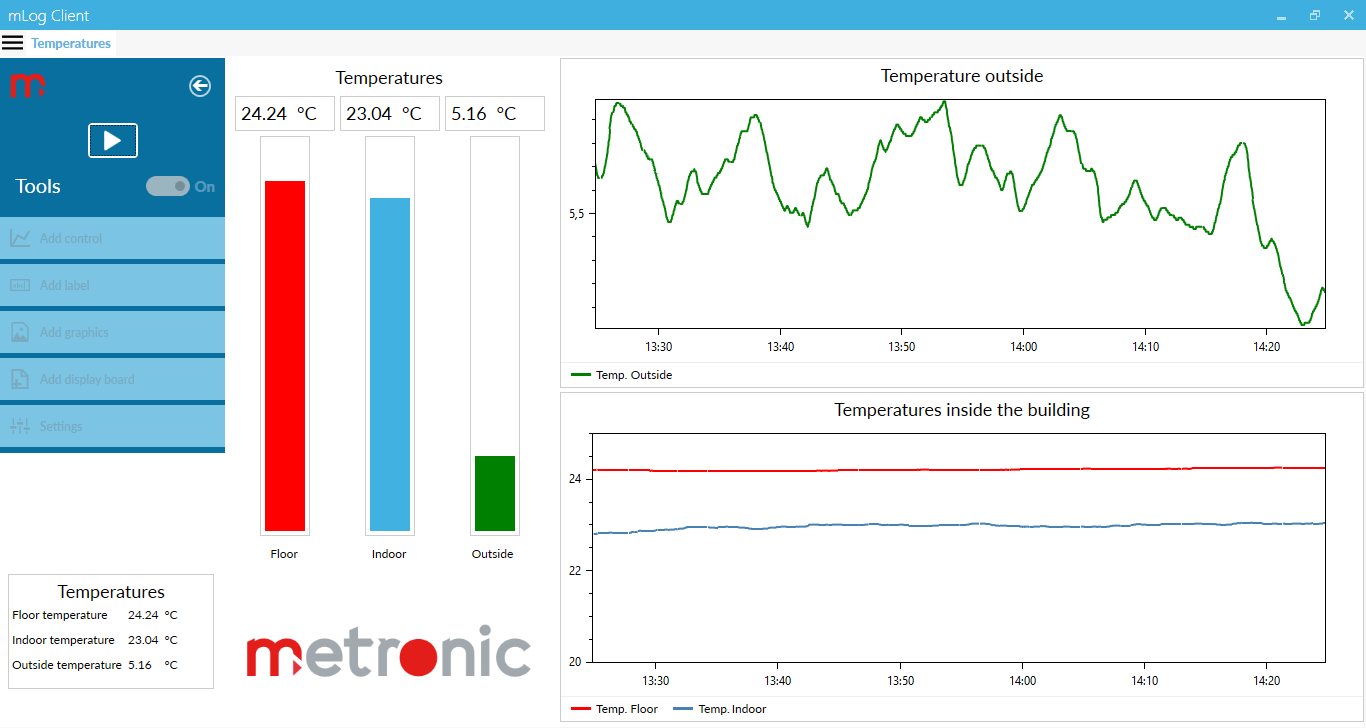
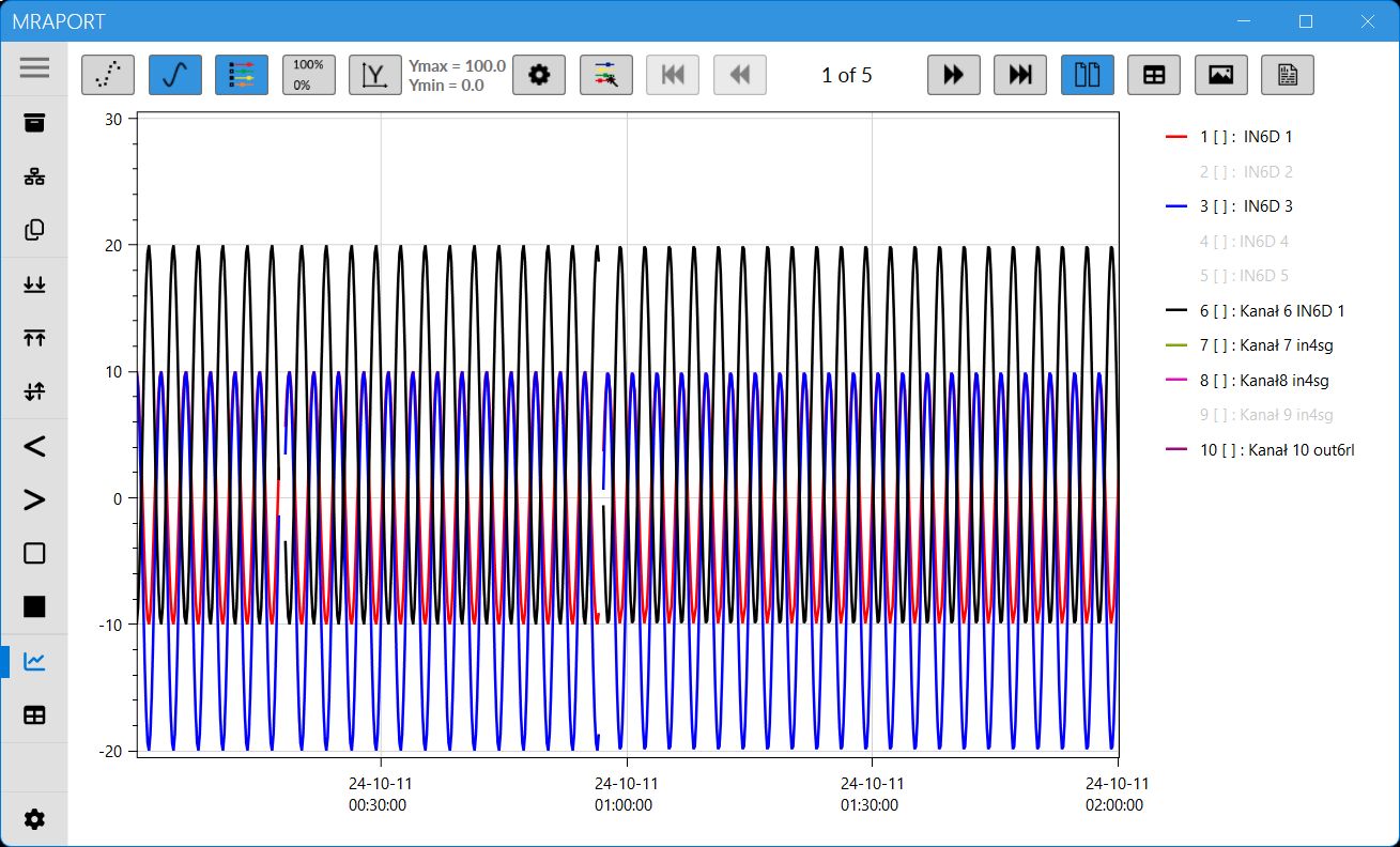
- Dedicated PC software for commissioning and archive data visualization
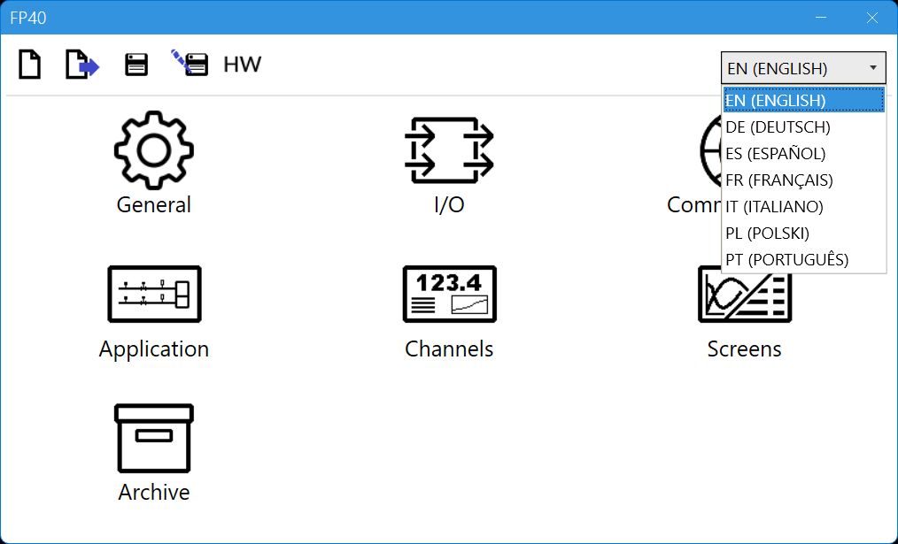
Available languages: EN, DE, ES, FR, IT, PL, PT
Applications for steam, liquids and technical gases
- For A, B main application setup one of possible applications using a configuration wizard:
- the flow and heat of a liquid medium
- the flow and delta heat of a liquid medium in a closed supply-return installation
- the flow and delta heat of a liquid medium in an installation with different supply and return flow rates
- the flow and heat of a steam
- the flow and heat of steam for steam-condensate conditions
- the flow and delta heat in a closed steam-condensate installation
- the flow and delta heat in a steam-condensate installation with different steam and condensate flow rates
- the flow and delta heat in a steam-generating installation with the supplied water flow rate measured
- the flow and heat of a technical gases
- The flow computer can work with:
- mass flowmeters
- volume flowmeters
- differential pressure devices with approximation by square root curve or differential pressure devices (orifices and nozzles) according to iteration algorithm according to PN-EN ISO 5167 standard (only for water and steam)
Inputs and channel types
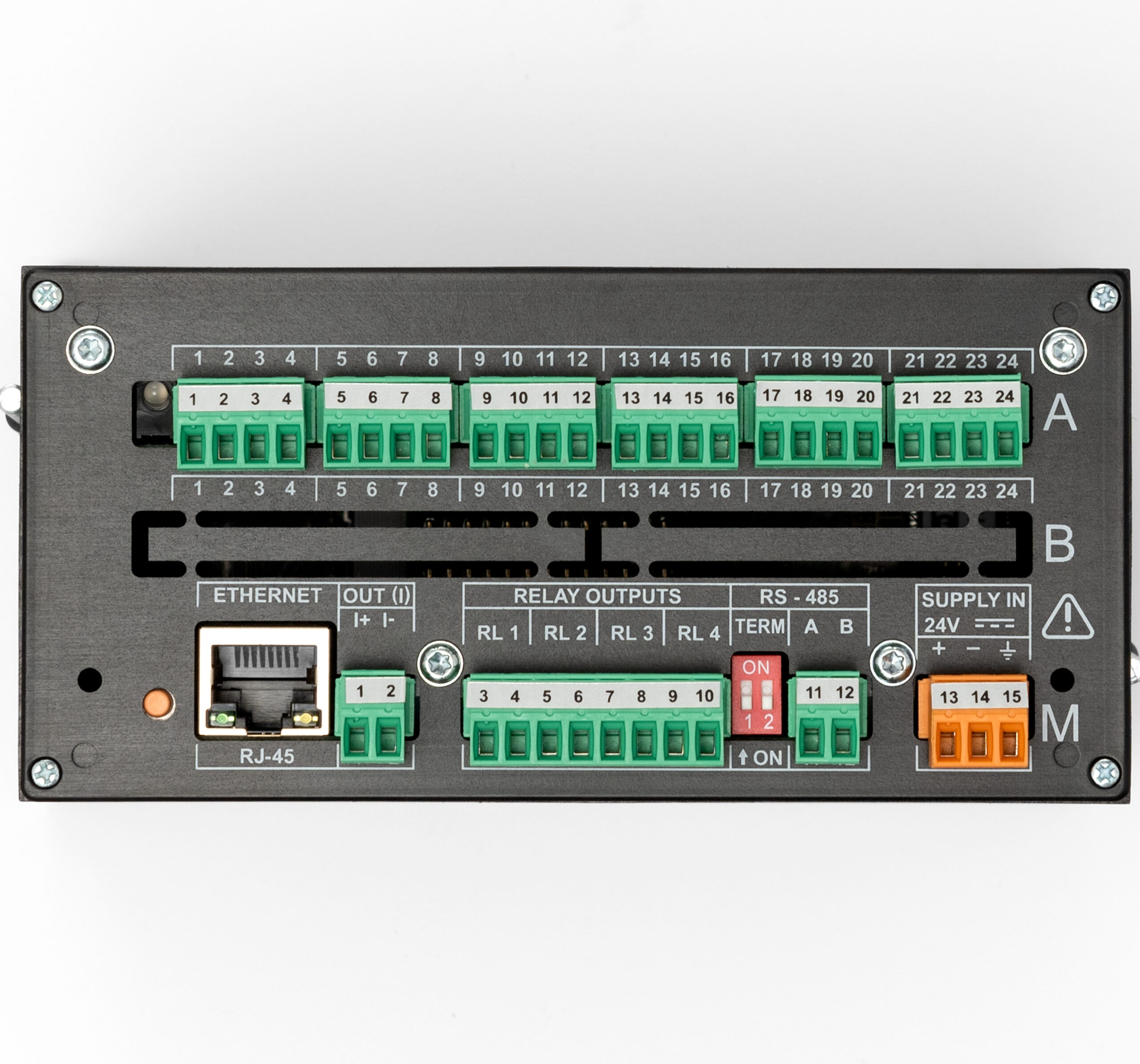
The FP40 can contain up to 12 analog inputs or HART and Modbus network modules. The FP40 in basic configuration has Ethernet port, RS-485 port, 4 alarm relays and one 4-20mA analog output and slots for two I/O modules from the table below. The computer has two measuring applications and up to 16 auxiliary channels that can be used as measuring or mathematical channels. The device enables power supply of the current loop for 0/4-20mA transducers. It is possible to define up to 10 user characteristics and up to eight additional user media, e.g. glycol, ammonia, heating oils.
Module inputs/outputs
- Module IN6I(24V) – six analog inputs with standard current loop output 0-20mA or
4-20mA powered from internal 24 VDC - Module IN6I – six analog inputs with standard current loop output 0-20mA or
4-20mA (or passive transmitters with external power supply) - Module IN6T – six analog inputs for connection temperature RTD sensors type Pt100, Pt200, Pt500, Pt1000, Ni100, Ni120, Ni1000, Cu50, Cu53, Cu100, KTY81, KTY83, KTY84 and connection thermocouples TC type J, L, K, U, E, N, B, R and S; and linear measurement of resistance
0 .. 4500 Ω or voltage -140 .. +140 mV - Module IN6V – six analog inputs for connecting as standard -10 .. +10 V, 0..10 V, 2 .. 10 V, 0 .. 5 V, 1 .. 5 V
- Module IN6 – six analog inputs, inputs 1-3 enable connection of RTD temperature sensors, TC thermocouples and linear measurement of resistance
0 .. 4000 Ω or -140 .. +140 mV, inputs 4-6 enable the connection of transducers in the 0 / 4-20mA standard, 0 / 2-10V, 0 / 1-5V - Module IN4SG – four analog inputs +/-30 mV for direct connection of strain gauges with a sensitivity of 1, 2, 4 mV / V or other, four discrete inputs for resetting (tare) analog inputs, power supply for strain gauges 5 VDC
- Module IN6D – six binary inputs for status tracking, frequency measurement (0.1 .. 1000 Hz), pulse counting (0 .. 100 Hz) with the possibility of powering transducers
- Module IN3D – three binary inputs for status tracking, frequency measurement (0.1 .. 12 500 Hz), pulse counting (0 .. 100 Hz) with the possibility of powering transducers
- Module 2RS485(24V) – two independent and galvanically separated RS-485 ports for reading transducers or other devices operating in the Modbus RTU standard; extra 24VDC voltage source power supply for external transducers
- Module 2RS485 – two independent and galvanically separated RS-485 ports for reading transducers or other devices operating in the Modbus RTU standard
- Module 1HRT – one HART (4-20 mA) port with the possibility of powering transmitters, operating in the Primary Master mode or in the Secondary Master mode
- Module OUT6RL – six solid state relays output rated at 24 VAC / 0.5 A or
36 VDC / 0.5 A - Module OUT3 – three programmable analogue outputs 0/4-20mA, 0/1-5V, 0/2-10V
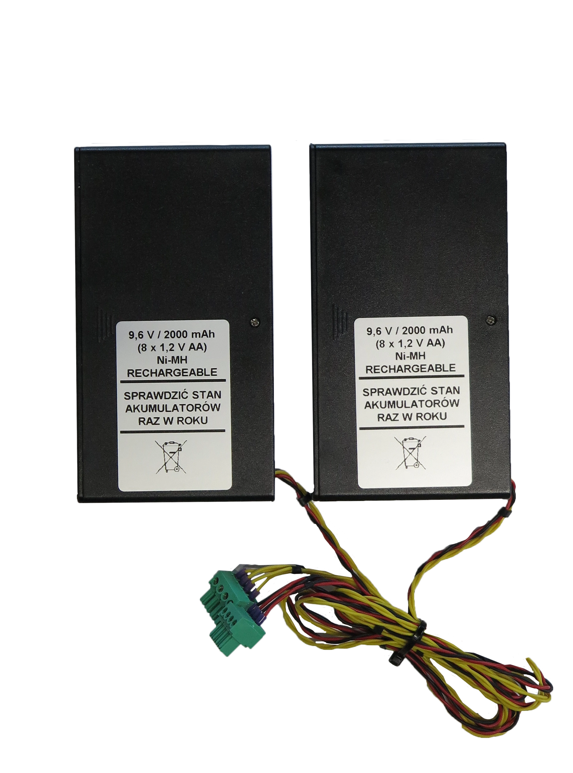
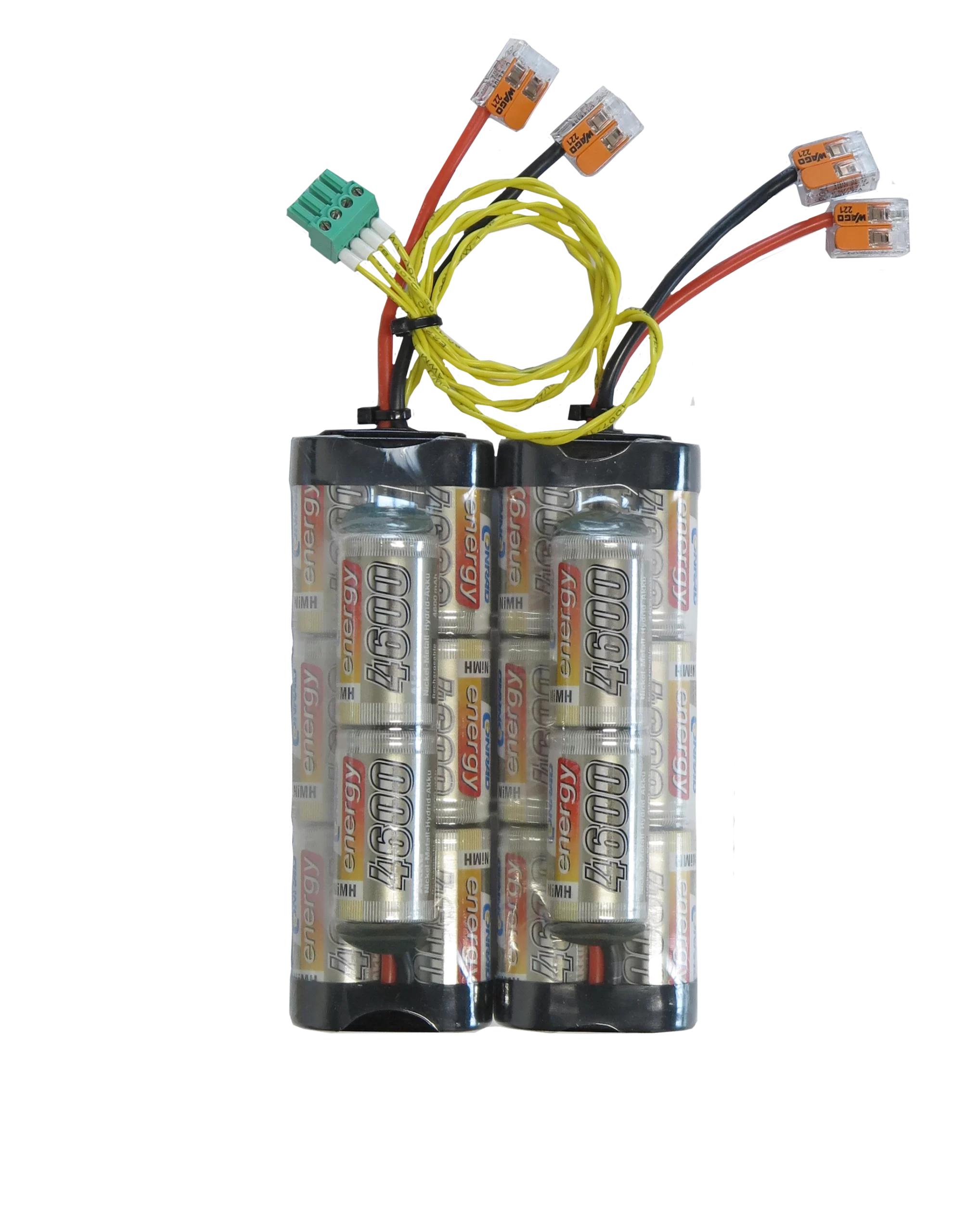
- Module PSBATT – supplying the device with NiMH storage batteries in the event of voltage break (backup) or periodic operation with battery power supply (from 1 to 20 hours depending on the configuration)
Available options and ordering information
| FP40 | Slot A | Slot B | |
| -XX | -XX | Module code from the table above |
Example:
- FP40 with HART module and 6 inputs 4-20mA has a code: FP40-75-11
- FP40 with 6 inputs 4-20mA has code: FP40-11-0
The sign 0 in the above code means that one module is installed in the device (on slot A).
The scope of measurement of steam, water parameters and other media
- The flow and heat measurement of superheated or saturated steam or water are according to IAPWS-IF97 recommendations in the operating range of temperature 0 .. 800 ºC and absolute pressure 0.05 .. 16.52 MPa
- Flow and energy measurements of liquids other than water are performed in the range of tabular values entered by the user – density and enthalpy as function of temperature
- Measurement of technical gas flow according to the ideal gas equation
Totalizers
- Totalizers for energy and flow measurements (2 for each channel)
- Totalizers can be reset manually or automatically every day, week or month
- Over and under counters to be realized in additional channels X
Alarms and control
- 2 alarm thresholds for each result
- Alarm or control mode, signaling failure of sensors connected to analogue inputs
- 4 solid state relays rated at 0.1 A/60 V
- E-mail messages about alarm states and cyclical reports with counter values (max. 5 recipients)
Recording measurement results
- Archive files:
process values (recording rate from 1 s up to 24 h)
totalizers values (record every 1 min up 24 h) - Event files: authorization log file, event log file, settings log file (recording after the occurrence of the event)
- 2 recording rates, toggled by alarm state for shorting/opening time of selected binary inputs
- Access to recorded data through USB port on the front panel or through Ethernet port
- Checksum secured files – protection against data manipulation
Technical specifications
| Front panel | |
| Type of display | LCD TFT 4” 800 px X 480 px
LED backlight |
| Display size | 86.4 mm X 52.5 mm |
| Keyboard | resistive touch panel |
| Additional indication | LED RGB |
| USB Port – front panel | |
| Version | USB 2.0 (with limited functionality, for connection of FLASH storage) |
| Connector type | USB standard ‘A’ type socket |
| Ethernet Port – rear panel | |
| Interface | 10/100 Base-T Ethernet |
| Connector type | RJ-45 |
| Transmission protocol | Server WWW, Modbus TCP Client/Server
ICMP (ping) |
| Modbus TCP Client | |
| Number of connections opened simultaneously | Max 20 |
| Number of read values | Max 30 |
| Modbus TCP Server | |
| Number of connections opened simultaneously | Max 4 |
| RS-485 Serial Port – rear panel | |
| Signals output on terminal block | A(+), B(-) |
| Galvanic separation | None |
| Maximum load | 32 receivers/transmitters |
| Transmission protocol | Modbus RTU Slave |
| Transmission rate | 1.2, 2.4, 4.8, 9.6, 19.2, 38.4, 57.6, 115.2 kbps |
| Parity control | Even, Odd, None |
| Frame | 1 start bit, 8 data bits, 1 stop bit |
| Maximum length of line | 1200 m |
| Internal terminating resistor | Vcc-A(+)-B(-)-G: 390 Ω – 220 Ω – 390 Ω
(activated by DIP-switches) |
| Maximum differntial voltage A(+), B(-) | -7 V .. +12 V |
| Minimum output signal of transmitter | 1.5 V (at RL= 54 W) |
| Minimum sensitivity of receiver | 200 mV / RIN= 12 kW |
| Minimum impedance of data transmission line | 54 W |
| Short-circuit/thermal protection | Yes/Yes |
| Internal data memory | |
| Memory type | Flash |
| Capacity | 2 GB |
| Estimated recording time for recording speed every 5 s for 16 measuring channels | ca. 2 years |
| Supply | |
| Supply voltage | 24 VDC (20 .. 30 VDC) |
| Maximum power consumption | 12 W |
| Security | The internal delay fuse 3.15 A, the exchange only by the service company |
| Electrical connections (terminal connectors) | |
| Type | screw terminal connectors |
| Wire cross section | solid and flexible: 0.14 .. 1.5 mm2
flexible with bootlace ferrule 0.25 .. 1.5 mm2 AWG 30 / 14 |
| Mechanical Dimensions – Housing | |
| Type of housing | panel mount, nonflammable plastic material „Noryl” |
| Dimensions with connectors (w X h w X d) | 144 mm X 72 mm X 127 mm |
| Dimensions of panel cut-out (w X h) | 138+1 mm X 68+0.7 mm |
| Maximum panel thickness | 5 mm |
| Weight | 0.5 kg |
| Protection class | IP30 on front panel side
IP20 on rear panel side |
| Environmental conditions | |
| Ambient temperature | 0 .. +50 °C or 0 .. +40 °C
depends on the device hardware configuration(1) |
| Relative humidity | 5 .. 95% (without steam condensation) |
| Maximum altitude | < 2000 m above sea level |
| Storage temperature | -30 .. +70 °C |
| Degree of pollution | PD2 |
| EMC | EMC Directive 2014/30/EU
EN 61326-1:2013 Table 2 (immunity) EN 61326-1:2013 Class A (emission) |
| RoHS | RoHS Directive 2011/65/EU |
| (1)If module IN6I(24V) or 2RS485(24V) installed and operating as a power supply source for external devices, ambient temperature is limited to 0 .. +40 °C. In all other configurations the ambient temperature range is 0 .. +50 °C. | |
| Analog output 4-20mA | |
| Output signal | 4-20 mA (3.6 .. 22 mA) |
| Current loop supply | no (external supply required) |
| Maximum voltage between I+ and I- | 28 VDC |
| Minimum supply current loop voltage | 9 VDC (RL = 0 Ω) |
| Loop resistance (RL) | 0 .. 500 Ω |
| Galvanic isolation to supply voltage | 250 VAC; 1500 VAC for 1 minute |
| Relay outputs | |
| Number of outputs | 4 |
| Outputs type | Solid state relays |
| Maximum voltage | 60 V AC/DC |
| Maximum load current | 0.1 A |


Flow computer for calculating compensated flow and thermal energy of steam, water and other liquid media
- Modular design of inputs and outputs
- Billing of 1 or 2 different measuring applications
- Auxiliary measurements and calculations
- Touchscreen 4″ colour LCD display
- Graphical diagram of the measuring application
- Math channels, functions +, -, /, *, √, ^
- Alarm and control functions
- 4 output relays (6 more optional)
- 1 analog output 4-20mA (3 more optional)
- Port Ethernet, Modbus TCP Client/Server
- Port RS–485, Modbus RTU Master/Slave
- USB port on the front panel
- Email message on alarms status and totalisers
- Dedicated PC software for commissioning and archive data visualization
Available languages: EN, DE, ES, FR, IT, PL, PT
Applications for steam, liquids and technical gases
- For A, B main application setup one of possible applications using a configuration wizard:
- the flow and heat of a liquid medium
- the flow and delta heat of a liquid medium in a closed supply-return installation
- the flow and delta heat of a liquid medium in an installation with different supply and return flow rates
- the flow and heat of a steam
- the flow and heat of steam for steam-condensate conditions
- the flow and delta heat in a closed steam-condensate installation
- the flow and delta heat in a steam-condensate installation with different steam and condensate flow rates
- the flow and delta heat in a steam-generating installation with the supplied water flow rate measured
- the flow and heat of a technical gases
- The flow computer can work with:
- mass flowmeters
- volume flowmeters
- differential pressure devices with approximation by square root curve or differential pressure devices (orifices and nozzles) according to iteration algorithm according to PN-EN ISO 5167 standard (only for water and steam)
Inputs and channel types
The FP40 can contain up to 12 analog inputs or HART and Modbus network modules. The FP40 in basic configuration has Ethernet port, RS-485 port, 4 alarm relays and one 4-20mA analog output and slots for two I/O modules from the table below. The computer has two measuring applications and up to 16 auxiliary channels that can be used as measuring or mathematical channels. The device enables power supply of the current loop for 0/4-20mA transducers. It is possible to define up to 10 user characteristics and up to eight additional user media, e.g. glycol, ammonia, heating oils.
Module inputs/outputs
- Module IN6I(24V) – six analog inputs with standard current loop output 0-20mA or
4-20mA powered from internal 24 VDC - Module IN6I – six analog inputs with standard current loop output 0-20mA or
4-20mA (or passive transmitters with external power supply) - Module IN6T – six analog inputs for connection temperature RTD sensors type Pt100, Pt200, Pt500, Pt1000, Ni100, Ni120, Ni1000, Cu50, Cu53, Cu100, KTY81, KTY83, KTY84 and connection thermocouples TC type J, L, K, U, E, N, B, R and S; and linear measurement of resistance
0 .. 4500 Ω or voltage -140 .. +140 mV - Module IN6V – six analog inputs for connecting as standard -10 .. +10 V, 0..10 V, 2 .. 10 V, 0 .. 5 V, 1 .. 5 V
- Module IN6 – six analog inputs, inputs 1-3 enable connection of RTD temperature sensors, TC thermocouples and linear measurement of resistance
0 .. 4000 Ω or -140 .. +140 mV, inputs 4-6 enable the connection of transducers in the 0 / 4-20mA standard, 0 / 2-10V, 0 / 1-5V - Module IN4SG – four analog inputs +/-30 mV for direct connection of strain gauges with a sensitivity of 1, 2, 4 mV / V or other, four discrete inputs for resetting (tare) analog inputs, power supply for strain gauges 5 VDC
- Module IN6D – six binary inputs for status tracking, frequency measurement (0.1 .. 1000 Hz), pulse counting (0 .. 100 Hz) with the possibility of powering transducers
- Module IN3D – three binary inputs for status tracking, frequency measurement (0.1 .. 12 500 Hz), pulse counting (0 .. 100 Hz) with the possibility of powering transducers
- Module 2RS485(24V) – two independent and galvanically separated RS-485 ports for reading transducers or other devices operating in the Modbus RTU standard; extra 24VDC voltage source power supply for external transducers
- Module 2RS485 – two independent and galvanically separated RS-485 ports for reading transducers or other devices operating in the Modbus RTU standard
- Module 1HRT – one HART (4-20 mA) port with the possibility of powering transmitters, operating in the Primary Master mode or in the Secondary Master mode
- Module OUT6RL – six solid state relays output rated at 24 VAC / 0.5 A or
36 VDC / 0.5 A - Module OUT3 – three programmable analogue outputs 0/4-20mA, 0/1-5V, 0/2-10V
- Module PSBATT – supplying the device with NiMH storage batteries in the event of voltage break (backup) or periodic operation with battery power supply (from 1 to 20 hours depending on the configuration)
Available options and ordering information
| FP40 | Slot A | Slot B | |
| -XX | -XX | Module code from the table above |
Example:
- FP40 with HART module and 6 inputs 4-20mA has a code: FP40-75-11
- FP40 with 6 inputs 4-20mA has code: FP40-11-0
The sign 0 in the above code means that one module is installed in the device (on slot A).
The scope of measurement of steam, water parameters and other media
- The flow and heat measurement of superheated or saturated steam or water are according to IAPWS-IF97 recommendations in the operating range of temperature 0 .. 800 ºC and absolute pressure 0.05 .. 16.52 MPa
- Flow and energy measurements of liquids other than water are performed in the range of tabular values entered by the user – density and enthalpy as function of temperature
- Measurement of technical gas flow according to the ideal gas equation
Totalizers
- Totalizers for energy and flow measurements (2 for each channel)
- Totalizers can be reset manually or automatically every day, week or month
- Over and under counters to be realized in additional channels X
Alarms and control
- 2 alarm thresholds for each result
- Alarm or control mode, signaling failure of sensors connected to analogue inputs
- 4 solid state relays rated at 0.1 A/60 V
- E-mail messages about alarm states and cyclical reports with counter values (max. 5 recipients)
Recording measurement results
- Archive files:
process values (recording rate from 1 s up to 24 h)
totalizers values (record every 1 min up 24 h) - Event files: authorization log file, event log file, settings log file (recording after the occurrence of the event)
- 2 recording rates, toggled by alarm state for shorting/opening time of selected binary inputs
- Access to recorded data through USB port on the front panel or through Ethernet port
- Checksum secured files – protection against data manipulation
Technical specifications
| Front panel | |
| Type of display | LCD TFT 4” 800 px X 480 px
LED backlight |
| Display size | 86.4 mm X 52.5 mm |
| Keyboard | resistive touch panel |
| Additional indication | LED RGB |
| USB Port – front panel | |
| Version | USB 2.0 (with limited functionality, for connection of FLASH storage) |
| Connector type | USB standard ‘A’ type socket |
| Ethernet Port – rear panel | |
| Interface | 10/100 Base-T Ethernet |
| Connector type | RJ-45 |
| Transmission protocol | Server WWW, Modbus TCP Client/Server
ICMP (ping) |
| Modbus TCP Client | |
| Number of connections opened simultaneously | Max 20 |
| Number of read values | Max 30 |
| Modbus TCP Server | |
| Number of connections opened simultaneously | Max 4 |
| RS-485 Serial Port – rear panel | |
| Signals output on terminal block | A(+), B(-) |
| Galvanic separation | None |
| Maximum load | 32 receivers/transmitters |
| Transmission protocol | Modbus RTU Slave |
| Transmission rate | 1.2, 2.4, 4.8, 9.6, 19.2, 38.4, 57.6, 115.2 kbps |
| Parity control | Even, Odd, None |
| Frame | 1 start bit, 8 data bits, 1 stop bit |
| Maximum length of line | 1200 m |
| Internal terminating resistor | Vcc-A(+)-B(-)-G: 390 Ω – 220 Ω – 390 Ω
(activated by DIP-switches) |
| Maximum differntial voltage A(+), B(-) | -7 V .. +12 V |
| Minimum output signal of transmitter | 1.5 V (at RL= 54 W) |
| Minimum sensitivity of receiver | 200 mV / RIN= 12 kW |
| Minimum impedance of data transmission line | 54 W |
| Short-circuit/thermal protection | Yes/Yes |
| Internal data memory | |
| Memory type | Flash |
| Capacity | 2 GB |
| Estimated recording time for recording speed every 5 s for 16 measuring channels | ca. 2 years |
| Supply | |
| Supply voltage | 24 VDC (20 .. 30 VDC) |
| Maximum power consumption | 12 W |
| Security | The internal delay fuse 3.15 A, the exchange only by the service company |
| Electrical connections (terminal connectors) | |
| Type | screw terminal connectors |
| Wire cross section | solid and flexible: 0.14 .. 1.5 mm2
flexible with bootlace ferrule 0.25 .. 1.5 mm2 AWG 30 / 14 |
| Mechanical Dimensions – Housing | |
| Type of housing | panel mount, nonflammable plastic material „Noryl” |
| Dimensions with connectors (w X h w X d) | 144 mm X 72 mm X 127 mm |
| Dimensions of panel cut-out (w X h) | 138+1 mm X 68+0.7 mm |
| Maximum panel thickness | 5 mm |
| Weight | 0.5 kg |
| Protection class | IP30 on front panel side
IP20 on rear panel side |
| Environmental conditions | |
| Ambient temperature | 0 .. +50 °C or 0 .. +40 °C
depends on the device hardware configuration(1) |
| Relative humidity | 5 .. 95% (without steam condensation) |
| Maximum altitude | < 2000 m above sea level |
| Storage temperature | -30 .. +70 °C |
| Degree of pollution | PD2 |
| EMC | EMC Directive 2014/30/EU
EN 61326-1:2013 Table 2 (immunity) EN 61326-1:2013 Class A (emission) |
| RoHS | RoHS Directive 2011/65/EU |
| (1)If module IN6I(24V) or 2RS485(24V) installed and operating as a power supply source for external devices, ambient temperature is limited to 0 .. +40 °C. In all other configurations the ambient temperature range is 0 .. +50 °C. | |
| Analog output 4-20mA | |
| Output signal | 4-20 mA (3.6 .. 22 mA) |
| Current loop supply | no (external supply required) |
| Maximum voltage between I+ and I- | 28 VDC |
| Minimum supply current loop voltage | 9 VDC (RL = 0 Ω) |
| Loop resistance (RL) | 0 .. 500 Ω |
| Galvanic isolation to supply voltage | 250 VAC; 1500 VAC for 1 minute |
| Relay outputs | |
| Number of outputs | 4 |
| Outputs type | Solid state relays |
| Maximum voltage | 60 V AC/DC |
| Maximum load current | 0.1 A |