Flow computer
- Up to 2 independent installations (A, B )
- Flows and energy balance calculations (systems X )
- 10 measurement inputs
- Math channels & functions (+, -, /, *, √)
- Alarm & control functions, 4 solid state relays (SSR)
- 4-20mA analogue output – one or two (option)
- Advanced data logging, recording data to the text files, 2 GB internal data memory
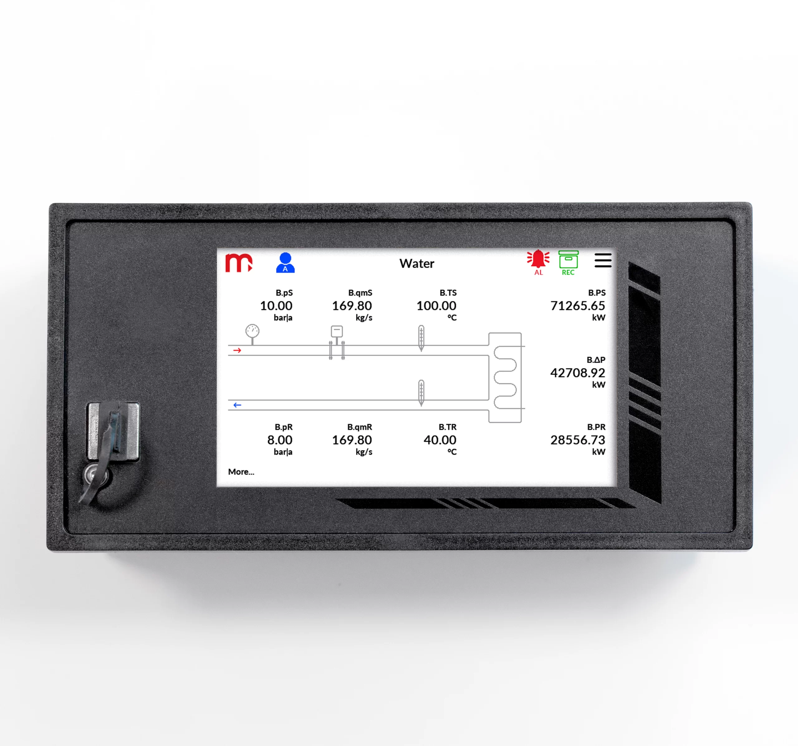
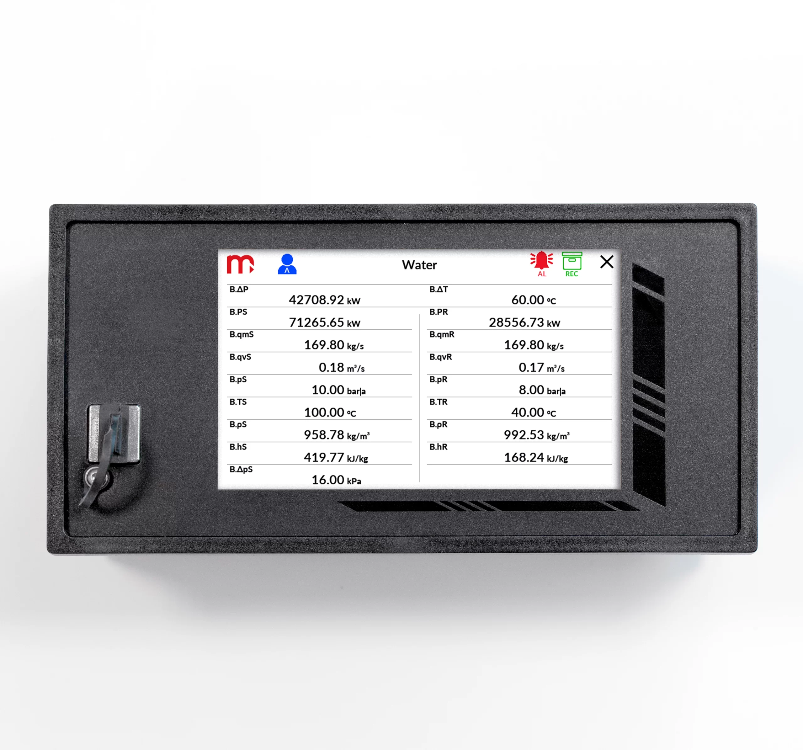
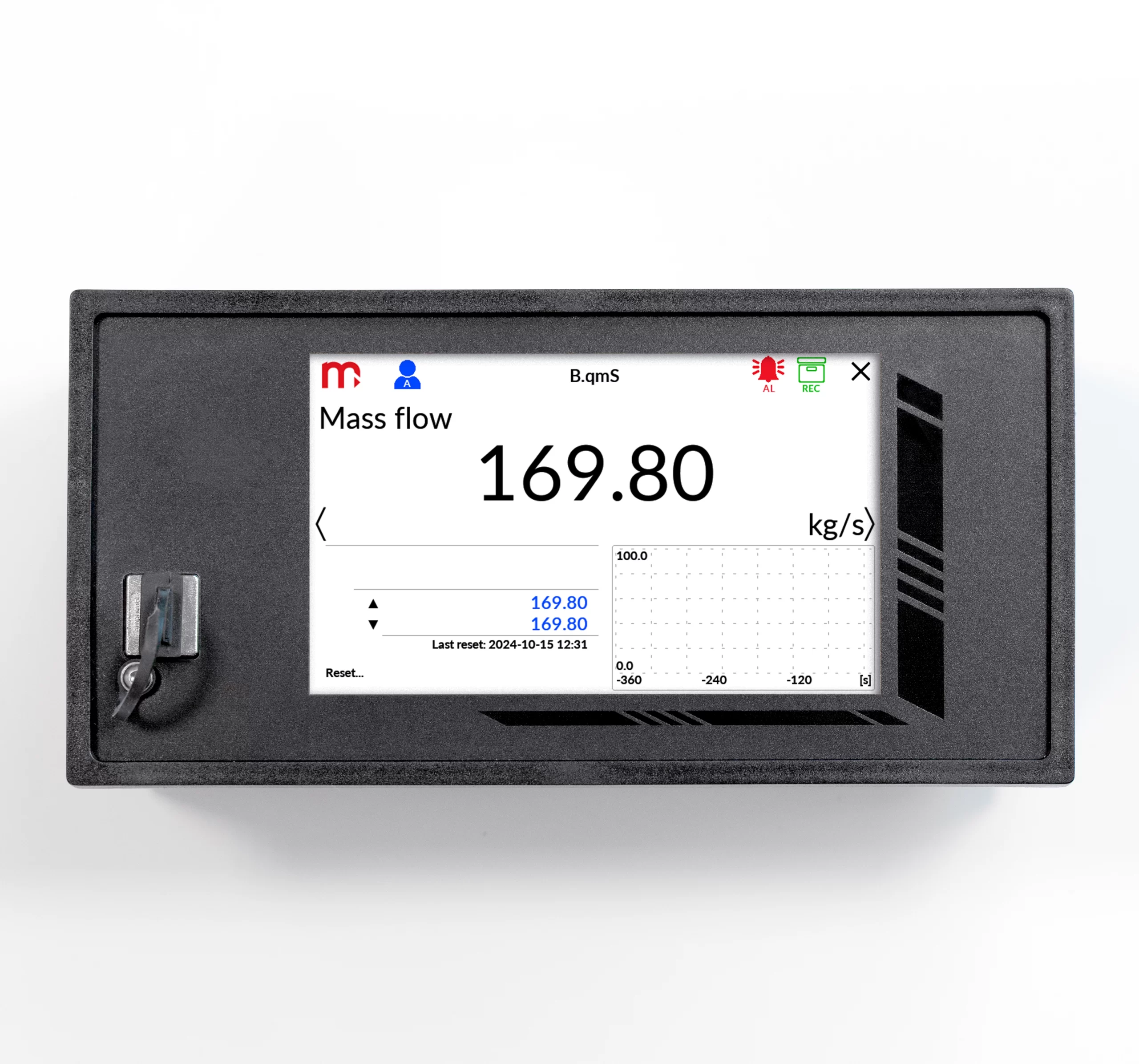
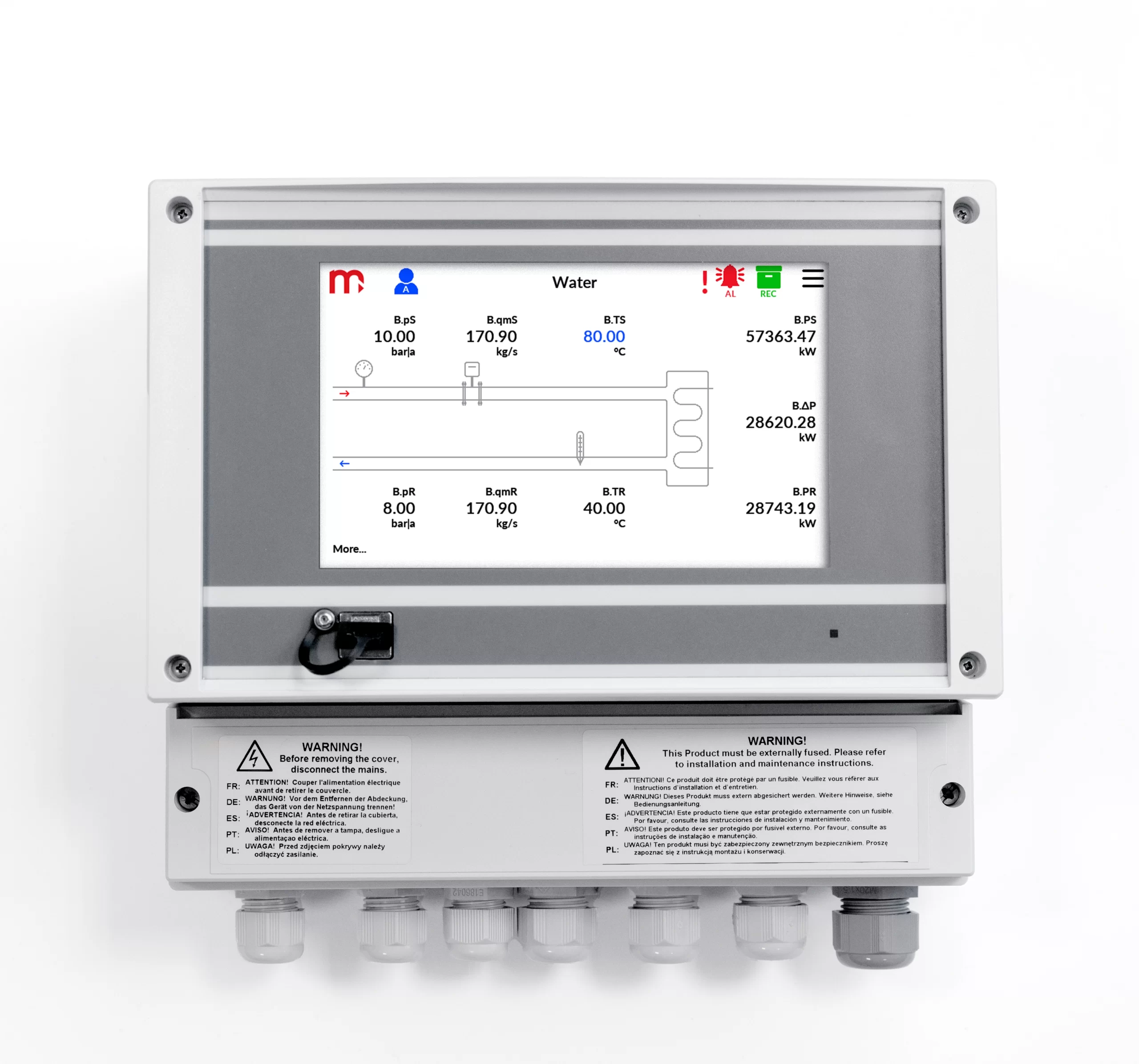
- User configurable data presentation, the colour TFT display
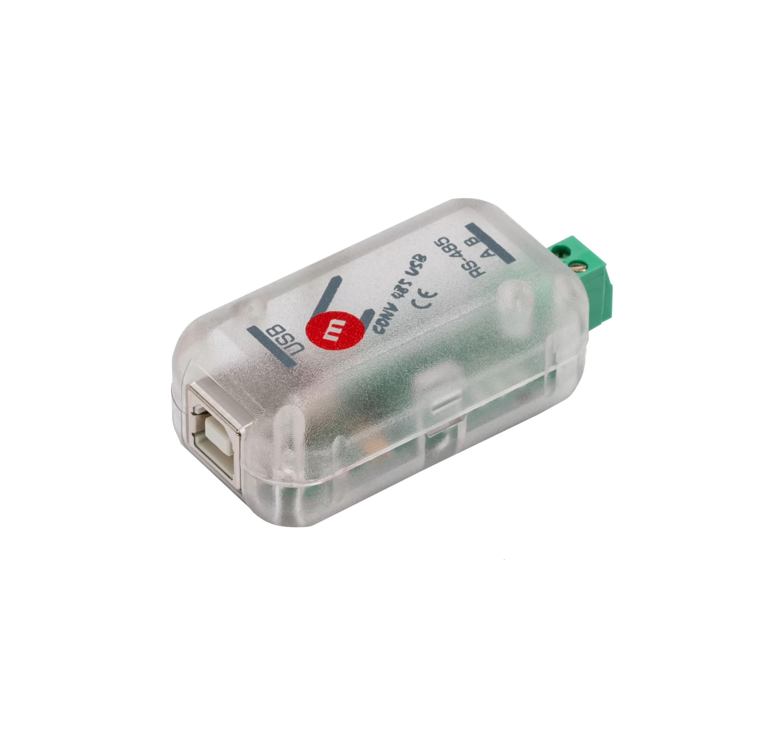
- RS-485 port (Modbus RTU)
- Ethernet port (Modbus TCP, www server)
- USB port on the front panel
- GSM module (option)
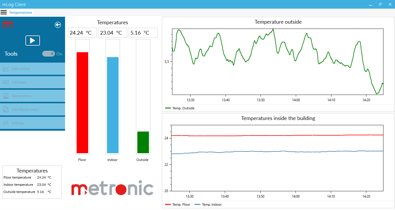
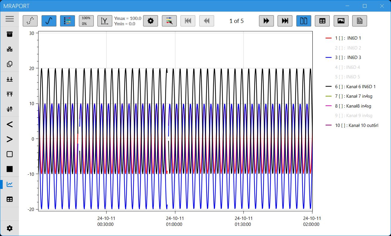
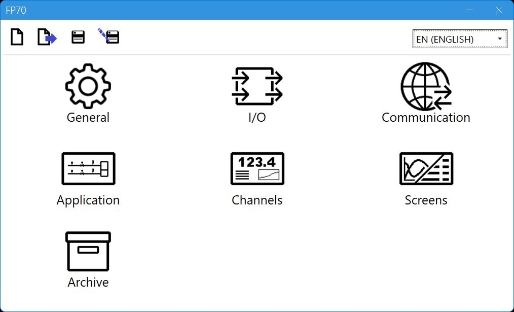
- Dedicated PC software for commissioning and archive data visualization
- Available languages: EN, DE, ES, FR, IT, PL, PT
Applications for steam, liquids and technical gases
- For A, B main application setup one of possible applications using a configuration wizard:
- the flow and heat of a liquid medium
- the flow and delta heat of a liquid medium in a closed supply-return installation
- the flow and delta heat of a liquid medium in an installation with different supply and return flow rates
- the flow and heat of a steam
- the flow and heat of steam for steam-condensate conditions
- the flow and delta heat in a closed steam-condensate installation
- the flow and delta heat in a steam-condensate installation with different steam and condensate flow rates
- the flow and delta heat in a steam-generating installation with the supplied water flow rate measured
- the flow and heat of a technical gases
Flow rate measurement
- The flow computer can work with:
- mass flowmeters
- volume flowmeters
- differential pressure devices with approximation by square root curve or differential pressure devices (orifices and nozzles) according to iteration algorithm according to
PN-EN ISO 5167 standard (only for water and steam)
Inputs and channels types
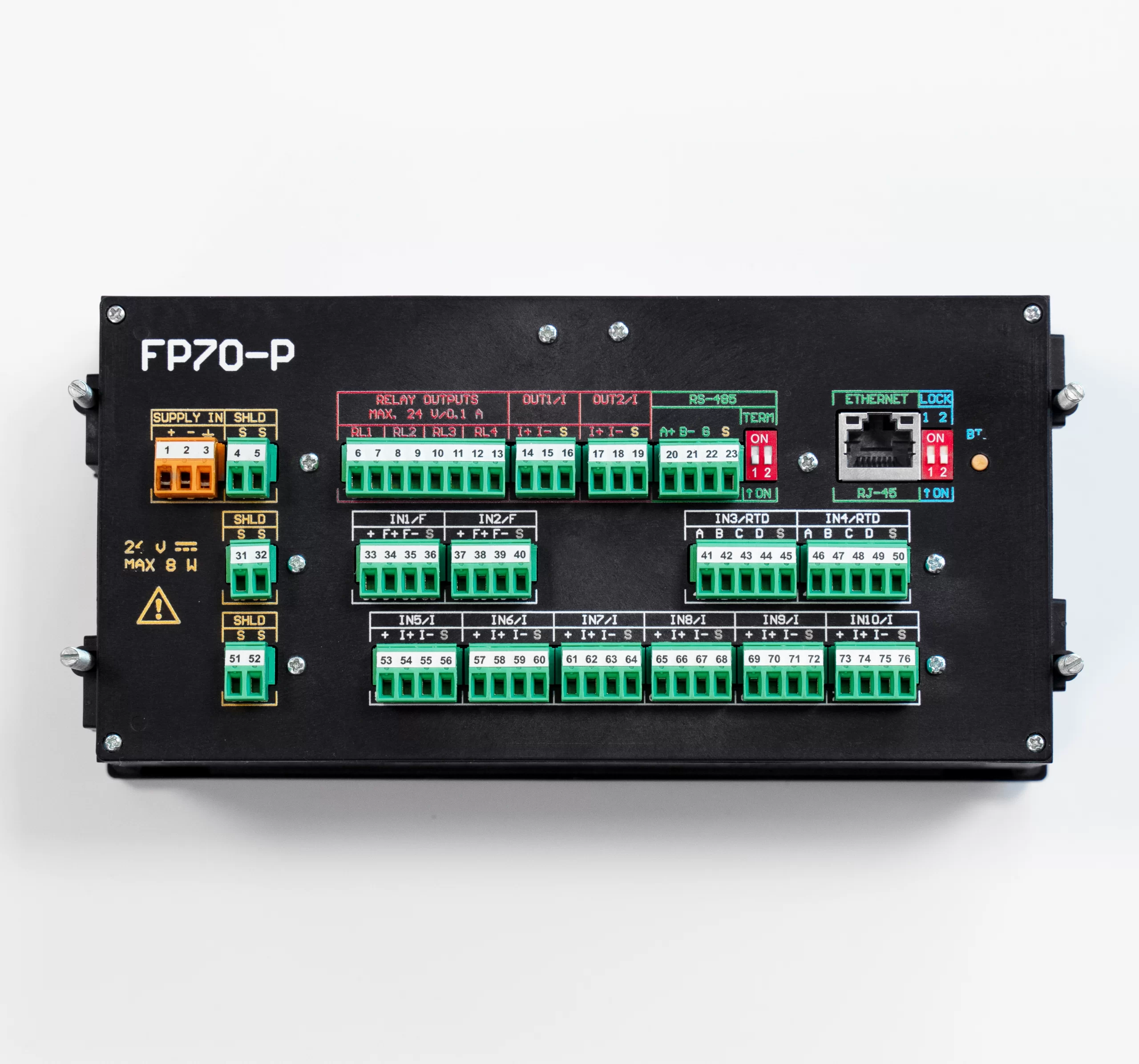
FP70P/FP70W has: 10 analogue inputs, Ethernet port and RS-485 port. In addition, 24 auxiliary channels are available, which can be used as measuring channels or as a math channels. The device enables supplying the current loop for 4-20mA transducers. Up to 10 User’s characteristics can be defined.
- 2 x RTD, two inputs adapted for connection of resistance temperature sensors (Pt100, Pt200, Pt500, Pt1000, Ni100, Ni120, Ni1000, Cu50, Cu53, Cu100, KTY81, KTY83, KTY84)
- 6 x I, six inputs for interaction with 0/4-20mA transducers only,
-
2 x PULS, two inputs intended for connection of transducers with a pulse output (range 0.02 Hz … 12,5 kHz).
Auxiliary channel
- 24 auxiliary channels, measurement of additional quantities or calculation of the formula entered by the user (available mathematical operations: addition, subtraction, multiplication, division, extract the root)
The scope of measurement of steam, water parameters and other media
- The flow and heat measurement of superheated or saturated steam or water are according to IAPWS-IF97 recommendations in the operating range of temperature 0 .. 800 ºC and absolute pressure 0.05 .. 16.52 MPa
- Flow and energy measurements of liquids other than water are performed in the range of tabular values entered by the user – density and enthalpy as function of temperature
- Measurement of technical gas flow according to the ideal gas equation
Totalizers
- Totalizers for energy and flow measurements (2 for each channel)
- Totalizers can be reset manually or automatically every day, week or month
- Over and under counters to be realized in additional channels X
Alarms and control
- 2 alarm thresholds for each result
- Alarm or control mode, signaling failure of sensors connected to analogue inputs
- 4 solid state relays rated at 0.1 A/60 V
- E-mail messages about alarm states and cyclical reports with counter values (max. 5 recipients)
Recording measurement results
- Archive files: process values (recording rate from 3 s up to 24 h), totalizers and min/average/max values (record every 1 h and every 24 h)
- Event files: authorization log file, event log file, settings log file (recording after the occurrence of the event)
- 2 recording rates, toggled by alarm state for shorting/opening time of selected binary inputs
- Access to recorded data through USB port on the front panel or through Ethernet port
- Checksum secured files – protection against data manipulation
| COMPENSATED FLOW AND HEAT ENERGY MEASUREMENT | |
| Accuracy of compensated steam, water, other liquid or technical gas flow | <2% (typowo <0,5%) |
| Frequency of measurement and calculation results | 0,5 s |
| FRONT PANEL | |
| Display type FP-70P | 5” LCD TFT colour 800x480px |
| Display type FP-70W | 7” LCD TFT colour 800x480px |
| Display size | 152mm x 91mm |
| LED indication | 3 colour LEDs |
| INPUTS ORGANIZATION | |
| FP70P, FP70W | 2 x PULS: IN1, IN2
2 x RTD: IN3, IN4 6 x I: IN5 – IN10 |
| RTD type analogue inputs | |
| Sensor type | Resistance (according to the table) |
| Measuring range | -200 .. +850 °C dla Pt100
-60 .. +150 °C dla Ni100 -180 ..+200 °C dla Cu100 |
| Sensor connection | 2, 3, or 4-wire |
| Wire resistance compensation | Manual, in range -99.99 .. +99.99 W |
| Maximum resistance of connecting wires | 20 W |
| A/D converter resolution | 24 bit |
| Accuracy (at Ta = +20 °C) | ± 0,5 °C (typowo ± 0,3 °C) |
| Temperature drift | Max ± 0,02 °C / °C |
| Galvanic isolation between inputs | No, common potential GND for all inputs |
| Galvanic isolation from supply voltage | 400 VAC (functional isolation) |
| 0/4-20mA type analogue inputs | |
| Signal type | 0-20mA lub 4-20mA |
| Transmitter connection | Passive (supplied from measuring loop) or active converter) |
| Input resistance | 12 W ±10% ? |
| Transmitters supply | 24 VDC / max 22 mA |
| A/D converter resolution | 24 bit |
| Accuracy (at Ta = +20 °C) | ±0.1% of the range (typically ±0.05% of the range) |
| Temperature drift | Max ±50 ppm / °C |
| Galvanic isolation between inputs | No, common potential GND for all inputs |
| Galvanic isolation from supply voltage | 400 VAC (functional isolation) |
| PULS type inputs (binary/pulse/frequency) | |
| Maximum input voltage | ±28 VDC |
| Galvanic isolation between inputs | No, common potential GND for all inputs |
| Galvanic isolation from supply voltage | 400 VAC (functional isolation) |
| Functions | State detection
Pulse counting Frequency measurement |
| Measuring range | 0,02 Hz do 12,5 kHz |
| Minimum impulse width | 20 ms
0.5 ms with filtrating capacitor |
| Accuracy (at Ta = +20 °C) | 0.02% |
| Configuration: OC/contact(1) | |
| Open circuit voltage | 12 V |
| Short circuit current | 12 mA |
| On/off threshold | 2.7 V / 2.4 V |
| (1)The default setting. | |
| Configuration: voltage input | |
| Input resistance | >10 kW |
| On/off threshold | 2.7 V / 2.4 V |
| Open circuit voltage | 12 V |
| Configuration: Namur | |
| High impedance state | 0.4 .. 1 mA |
| Low impedance state | 2.2 .. 6.5 mA |
| 4-20mA analogue output (optional) | |
| Number of outputs | 1 or 2 |
| Output signal | 4-20mA (3.6–22 mA) |
| Maximum voltage between I+ and I- | 28 VDC |
| Loop resistance (at Ucc = 24 V) | 0 .. 500 Ω |
| Converter resolution D/A | 16 bits |
| Accuracy | 0.5% |
| Current loop supply | External or internal power supply 24 VDC / 22 mA |
| Galvanic isolation between outputs | 400 VAC (functional isolation) |
| Galvanic isolation from supply voltage | 400 VAC (functional isolation) |
| Binary outputs (Solid State Relays) | |
| Number of outputs | 4 |
| Type of outputs | Solid State Relays |
| Maximum load current | 100 mA DC/AC |
| Maximum voltage | 60 V DC/AC |
| Galvanic isolation between outputs | 400 VAC (functional isolation) |
| Galvanic isolation from supply voltage | 400 VAC (functional isolation) |
| RS-485 serial port | |
| Maximum load | 32 receivers/transmitters |
| Maximum line length | 1200 m |
| Maximum differential voltage A(+) – B(-) | -7 .. +12 V |
| Maximum total voltage A(+) – ‘ground’ or B(-) – ‘ground’ |
-7 .. +12 V |
| Minimal output signal from transmitter | 1.5 V (for R0 = 54 W) |
| Minimum receiver sensitivity | 200 mV / RIN = 12 kW |
| Minimum impedance of data transmission line | 54 W |
| Internal terminating resistor | Yes, activated by short-circuit pins on terminal block |
| Short-circuit/thermal protection | Yes/Yes |
| Transmission protocol | Modbus RTU |
| Baud rate | 2.4, 4.8, 9.6 ,19.2, 38.4, 57.6, 115.2 kbps |
| Parity control | Even, Odd, None |
| Frame | 1 start bit, 8 data bits, 1 stop bit |
| Galvanic isolation | No |
| Ethernet port | |
| Transmission protocol | Modbus TCP, ICMP (ping), DHCP server, http server |
| Interface | 10BaseT Ethernet |
| Data buffer | 300 B |
| Number of opened connections (simultaneously) | 4 |
| Connector type | RJ-45 |
| LED signaling | 2, build in RJ-45 socked |
| USB port | |
| Socket type | A type, according to USB standard |
| Version | USB 2.0 |
| Socket protection class | IP54 |
| Recording format | FAT16 (within a limited scope) |
| Recording indication | red-orange-green LED on the front panel |
| FP70P power supply | |
| Supply voltage | 24 VDC (15 .. 30 VDC) |
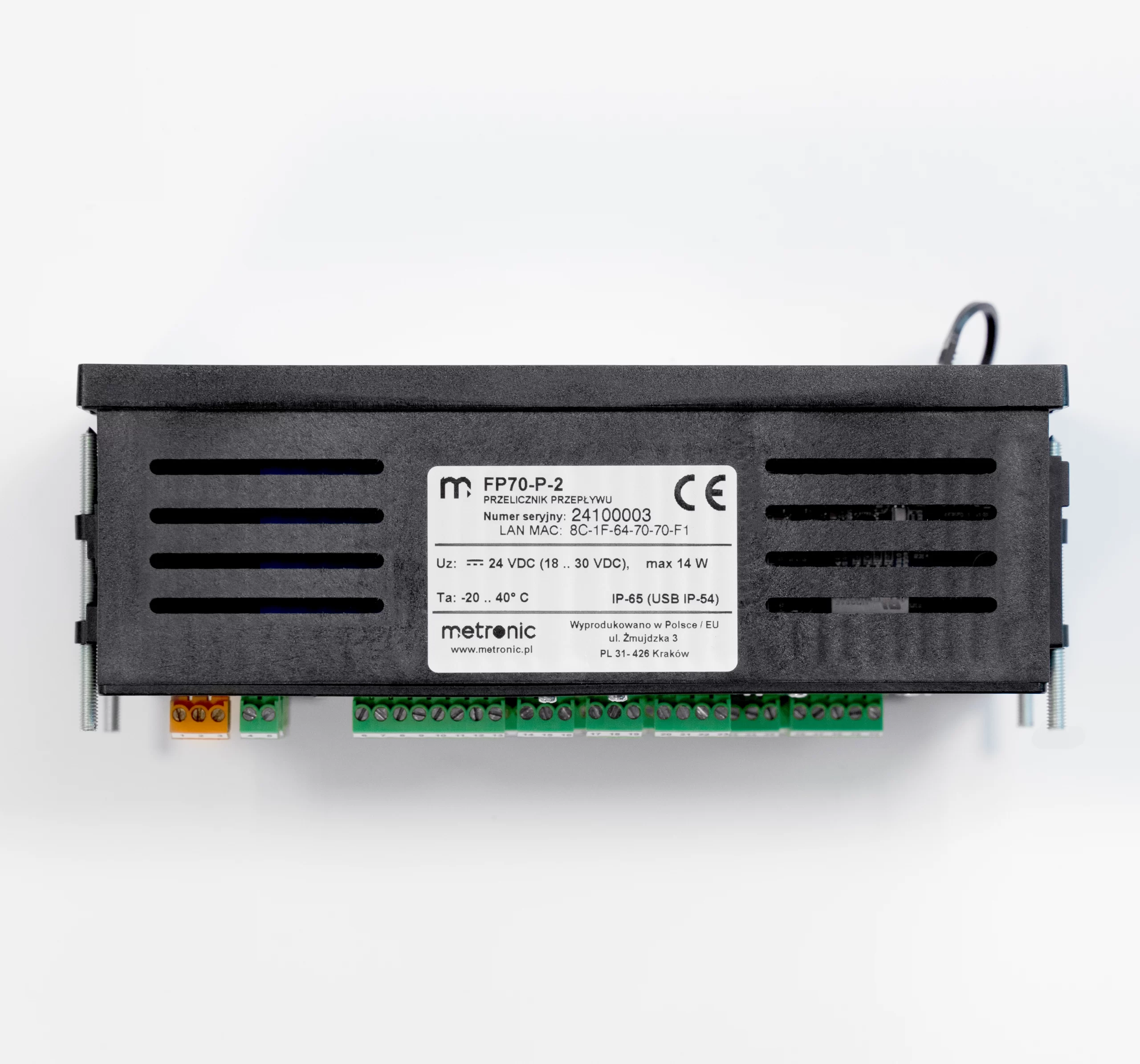
| Maximum power consumption | 14 VA / 14 W |
| FP70W power supply | |
| Supply voltage | 100 .. 240 VAC 50/60 Hz
24 VDC (15 .. 30 VDC) |
| Maximum power consumption | 28 VA / 28 W (for 100 .. 240 VAC power supply)
14 VA / 14 W (for 24 VAC/VDC power supply) |
| Wire terminals | |
| Type | · FP70P: screw type terminal blocks
· FP70W: spring type terminal block |
| Conductor cross section | · FP70P: solid max. 1.5 mm2
· FP70W: stranded 0.2 .. 1.5 mm2 |
| FP70P enclosure – dimensions | |
| Enclosure type | Panel mount, nonflammable plastic material ‘Noryl’ |
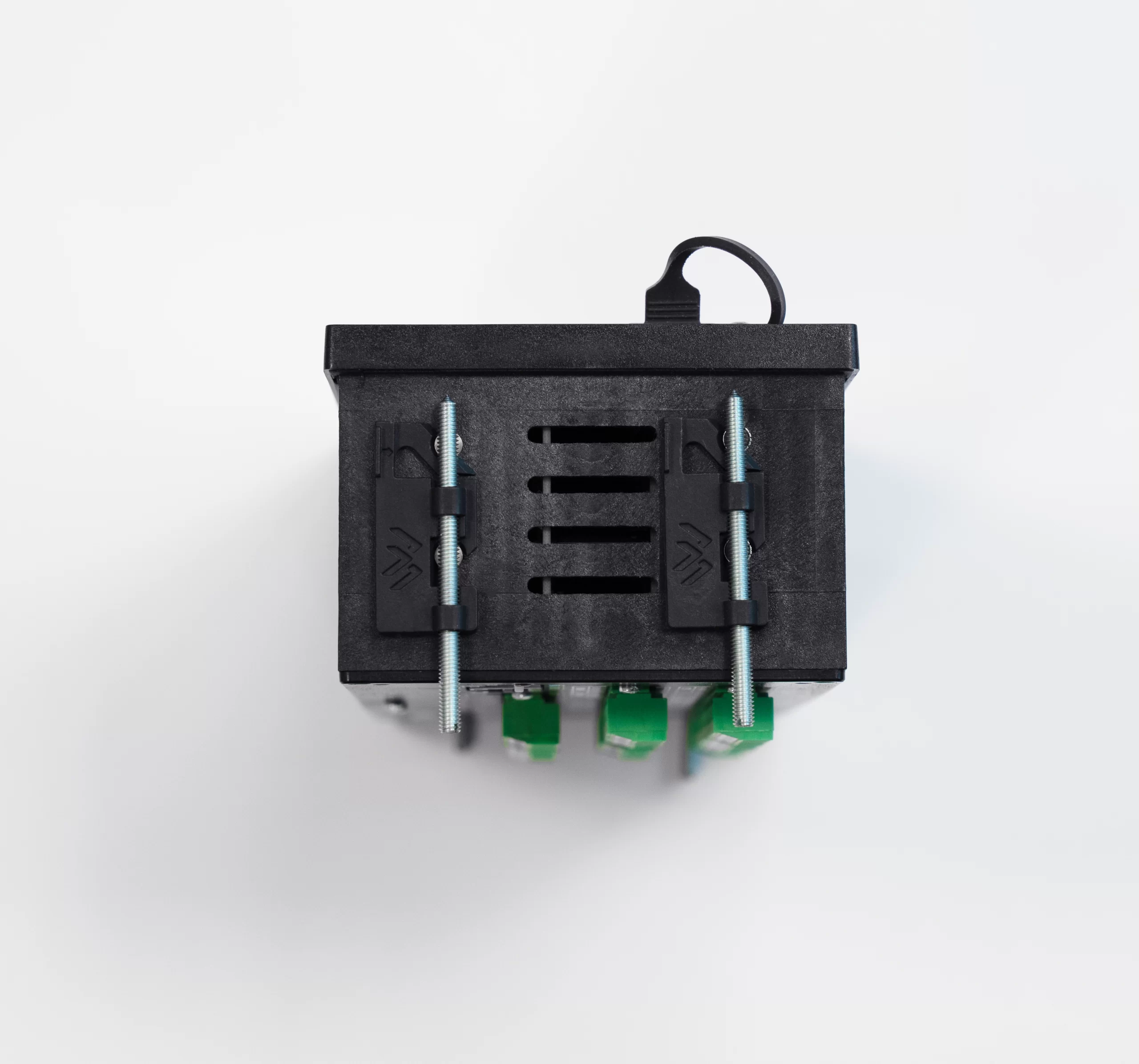
| Dimensions (width x height x depth) | 192 mm x 96 mm x 63.5 mm |
| Enclosure depth with terminals | ca. 72 mm |
| Panel cut-out dimensions (width x height) | 186+1.1 mm x 92+0.6 mm |
| Panel maximum thickness | 5 mm |
| Weight | ca. 0.7 kg |
| Protection class from the front panel | IP54 |
| Protection class from the rear panel | IP30 |
| FP70W enclosure – dimensions | |
| Enclosure type | Wall mount, PC material |
| Dimensions (width x height x depth) | 257 mm x 217 mm x 125 mm (without cable glands)
257 mm x 247 mm x 125 mm (with cable glands) |
| Weight | ca. 2.1 kg |
| Protection class | IP54 |
| FP70P environmental conditions | |
| Ambient temperature | 0 .. +40 °C |
| Relative humidity | 0 .. 75% (without steam condensation) |
| Storage temperature | -20 .. +80 °C |
| Overvoltage category | OV II |
| Pollution degree | PD 2 |
| LVD (safety) | EN 61010-1 |
| EMC | Directive 2014/30/EU:
· immunity for industrial environments according to EN 61326-1:2013 (Table 2) · conductive and radiated emissions Class A equipment according to EN 61326-1:2013 |
| RoHS | Directive 2011/65/EU |
| Installation location | Indoor only |
| FP70W environmental conditions | |
| Ambient temperature | -20 .. +40 °C |
| Relative humidity | 0 .. 75% (without steam condensation) |
| Storage temperature | -20 .. +80 °C |
| Overvoltage category | OV II |
| Pollution degree | PD 2 |
| LVD (safety) | EN 61010-1 |
| EMC | Directive 2014/30/EU:
· immunity for industrial environments according to EN 61326-1:2013 (Table 2) · conductive and radiated emissions Class A equipment according to EN 61326-1:2013 |
| RoHS | Directive 2011/65/EU |
| Installation location | Indoor or outdoor(2) |
| (2)If additional protection against atmospheric precipitation is provided (roofing), the device can be installed outdoor. | |










Flow computer
- Up to 2 independent installations (A, B )
- Flows and energy balance calculations (systems X )
- 10 measurement inputs
- Math channels & functions (+, -, /, *, √)
- Alarm & control functions, 4 solid state relays (SSR)
- 4-20mA analogue output – one or two (option)
- Advanced data logging, recording data to the text files, 2 GB internal data memory
- User configurable data presentation, the colour TFT display
- RS-485 port (Modbus RTU)
- Ethernet port (Modbus TCP, www server)
- USB port on the front panel
- GSM module (option)
- Dedicated PC software for commissioning and archive data visualization
- Available languages: EN, DE, ES, FR, IT, PL, PT
Applications for steam, liquids and technical gases
- For A, B main application setup one of possible applications using a configuration wizard:
- the flow and heat of a liquid medium
- the flow and delta heat of a liquid medium in a closed supply-return installation
- the flow and delta heat of a liquid medium in an installation with different supply and return flow rates
- the flow and heat of a steam
- the flow and heat of steam for steam-condensate conditions
- the flow and delta heat in a closed steam-condensate installation
- the flow and delta heat in a steam-condensate installation with different steam and condensate flow rates
- the flow and delta heat in a steam-generating installation with the supplied water flow rate measured
- the flow and heat of a technical gases
Flow rate measurement
- The flow computer can work with:
- mass flowmeters
- volume flowmeters
- differential pressure devices with approximation by square root curve or differential pressure devices (orifices and nozzles) according to iteration algorithm according to
PN-EN ISO 5167 standard (only for water and steam)
Inputs and channels types
FP70P/FP70W has: 10 analogue inputs, Ethernet port and RS-485 port. In addition, 24 auxiliary channels are available, which can be used as measuring channels or as a math channels. The device enables supplying the current loop for 4-20mA transducers. Up to 10 User’s characteristics can be defined.
- 2 x RTD, two inputs adapted for connection of resistance temperature sensors (Pt100, Pt200, Pt500, Pt1000, Ni100, Ni120, Ni1000, Cu50, Cu53, Cu100, KTY81, KTY83, KTY84)
- 6 x I, six inputs for interaction with 0/4-20mA transducers only,
-
2 x PULS, two inputs intended for connection of transducers with a pulse output (range 0.02 Hz … 12,5 kHz).
Auxiliary channel
- 24 auxiliary channels, measurement of additional quantities or calculation of the formula entered by the user (available mathematical operations: addition, subtraction, multiplication, division, extract the root)
The scope of measurement of steam, water parameters and other media
- The flow and heat measurement of superheated or saturated steam or water are according to IAPWS-IF97 recommendations in the operating range of temperature 0 .. 800 ºC and absolute pressure 0.05 .. 16.52 MPa
- Flow and energy measurements of liquids other than water are performed in the range of tabular values entered by the user – density and enthalpy as function of temperature
- Measurement of technical gas flow according to the ideal gas equation
Totalizers
- Totalizers for energy and flow measurements (2 for each channel)
- Totalizers can be reset manually or automatically every day, week or month
- Over and under counters to be realized in additional channels X
Alarms and control
- 2 alarm thresholds for each result
- Alarm or control mode, signaling failure of sensors connected to analogue inputs
- 4 solid state relays rated at 0.1 A/60 V
- E-mail messages about alarm states and cyclical reports with counter values (max. 5 recipients)
Recording measurement results
- Archive files: process values (recording rate from 3 s up to 24 h), totalizers and min/average/max values (record every 1 h and every 24 h)
- Event files: authorization log file, event log file, settings log file (recording after the occurrence of the event)
- 2 recording rates, toggled by alarm state for shorting/opening time of selected binary inputs
- Access to recorded data through USB port on the front panel or through Ethernet port
- Checksum secured files – protection against data manipulation

| COMPENSATED FLOW AND HEAT ENERGY MEASUREMENT | |
| Accuracy of compensated steam, water, other liquid or technical gas flow | <2% (typowo <0,5%) |
| Frequency of measurement and calculation results | 0,5 s |
| FRONT PANEL | |
| Display type FP-70P | 5” LCD TFT colour 800x480px |
| Display type FP-70W | 7” LCD TFT colour 800x480px |
| Display size | 152mm x 91mm |
| LED indication | 3 colour LEDs |
| INPUTS ORGANIZATION | |
| FP70P, FP70W | 2 x PULS: IN1, IN2
2 x RTD: IN3, IN4 6 x I: IN5 – IN10 |
| RTD type analogue inputs | |
| Sensor type | Resistance (according to the table) |
| Measuring range | -200 .. +850 °C dla Pt100
-60 .. +150 °C dla Ni100 -180 ..+200 °C dla Cu100 |
| Sensor connection | 2, 3, or 4-wire |
| Wire resistance compensation | Manual, in range -99.99 .. +99.99 W |
| Maximum resistance of connecting wires | 20 W |
| A/D converter resolution | 24 bit |
| Accuracy (at Ta = +20 °C) | ± 0,5 °C (typowo ± 0,3 °C) |
| Temperature drift | Max ± 0,02 °C / °C |
| Galvanic isolation between inputs | No, common potential GND for all inputs |
| Galvanic isolation from supply voltage | 400 VAC (functional isolation) |
| 0/4-20mA type analogue inputs | |
| Signal type | 0-20mA lub 4-20mA |
| Transmitter connection | Passive (supplied from measuring loop) or active converter) |
| Input resistance | 12 W ±10% ? |
| Transmitters supply | 24 VDC / max 22 mA |
| A/D converter resolution | 24 bit |
| Accuracy (at Ta = +20 °C) | ±0.1% of the range (typically ±0.05% of the range) |
| Temperature drift | Max ±50 ppm / °C |
| Galvanic isolation between inputs | No, common potential GND for all inputs |
| Galvanic isolation from supply voltage | 400 VAC (functional isolation) |
| PULS type inputs (binary/pulse/frequency) | |
| Maximum input voltage | ±28 VDC |
| Galvanic isolation between inputs | No, common potential GND for all inputs |
| Galvanic isolation from supply voltage | 400 VAC (functional isolation) |
| Functions | State detection
Pulse counting Frequency measurement |
| Measuring range | 0,02 Hz do 12,5 kHz |
| Minimum impulse width | 20 ms
0.5 ms with filtrating capacitor |
| Accuracy (at Ta = +20 °C) | 0.02% |
| Configuration: OC/contact(1) | |
| Open circuit voltage | 12 V |
| Short circuit current | 12 mA |
| On/off threshold | 2.7 V / 2.4 V |
| (1)The default setting. | |
| Configuration: voltage input | |
| Input resistance | >10 kW |
| On/off threshold | 2.7 V / 2.4 V |
| Open circuit voltage | 12 V |
| Configuration: Namur | |
| High impedance state | 0.4 .. 1 mA |
| Low impedance state | 2.2 .. 6.5 mA |
| 4-20mA analogue output (optional) | |
| Number of outputs | 1 or 2 |
| Output signal | 4-20mA (3.6–22 mA) |
| Maximum voltage between I+ and I- | 28 VDC |
| Loop resistance (at Ucc = 24 V) | 0 .. 500 Ω |
| Converter resolution D/A | 16 bits |
| Accuracy | 0.5% |
| Current loop supply | External or internal power supply 24 VDC / 22 mA |
| Galvanic isolation between outputs | 400 VAC (functional isolation) |
| Galvanic isolation from supply voltage | 400 VAC (functional isolation) |
| Binary outputs (Solid State Relays) | |
| Number of outputs | 4 |
| Type of outputs | Solid State Relays |
| Maximum load current | 100 mA DC/AC |
| Maximum voltage | 60 V DC/AC |
| Galvanic isolation between outputs | 400 VAC (functional isolation) |
| Galvanic isolation from supply voltage | 400 VAC (functional isolation) |
| RS-485 serial port | |
| Maximum load | 32 receivers/transmitters |
| Maximum line length | 1200 m |
| Maximum differential voltage A(+) – B(-) | -7 .. +12 V |
| Maximum total voltage A(+) – ‘ground’ or B(-) – ‘ground’ |
-7 .. +12 V |
| Minimal output signal from transmitter | 1.5 V (for R0 = 54 W) |
| Minimum receiver sensitivity | 200 mV / RIN = 12 kW |
| Minimum impedance of data transmission line | 54 W |
| Internal terminating resistor | Yes, activated by short-circuit pins on terminal block |
| Short-circuit/thermal protection | Yes/Yes |
| Transmission protocol | Modbus RTU |
| Baud rate | 2.4, 4.8, 9.6 ,19.2, 38.4, 57.6, 115.2 kbps |
| Parity control | Even, Odd, None |
| Frame | 1 start bit, 8 data bits, 1 stop bit |
| Galvanic isolation | No |
| Ethernet port | |
| Transmission protocol | Modbus TCP, ICMP (ping), DHCP server, http server |
| Interface | 10BaseT Ethernet |
| Data buffer | 300 B |
| Number of opened connections (simultaneously) | 4 |
| Connector type | RJ-45 |
| LED signaling | 2, build in RJ-45 socked |
| USB port | |
| Socket type | A type, according to USB standard |
| Version | USB 2.0 |
| Socket protection class | IP54 |
| Recording format | FAT16 (within a limited scope) |
| Recording indication | red-orange-green LED on the front panel |
| FP70P power supply | |
| Supply voltage | 24 VDC (15 .. 30 VDC) |
| Maximum power consumption | 14 VA / 14 W |
| FP70W power supply | |
| Supply voltage | 100 .. 240 VAC 50/60 Hz
24 VDC (15 .. 30 VDC) |
| Maximum power consumption | 28 VA / 28 W (for 100 .. 240 VAC power supply)
14 VA / 14 W (for 24 VAC/VDC power supply) |
| Wire terminals | |
| Type | · FP70P: screw type terminal blocks
· FP70W: spring type terminal block |
| Conductor cross section | · FP70P: solid max. 1.5 mm2
· FP70W: stranded 0.2 .. 1.5 mm2 |
| FP70P enclosure – dimensions | |
| Enclosure type | Panel mount, nonflammable plastic material ‘Noryl’ |
| Dimensions (width x height x depth) | 192 mm x 96 mm x 63.5 mm |
| Enclosure depth with terminals | ca. 72 mm |
| Panel cut-out dimensions (width x height) | 186+1.1 mm x 92+0.6 mm |
| Panel maximum thickness | 5 mm |
| Weight | ca. 0.7 kg |
| Protection class from the front panel | IP54 |
| Protection class from the rear panel | IP30 |
| FP70W enclosure – dimensions | |
| Enclosure type | Wall mount, PC material |
| Dimensions (width x height x depth) | 257 mm x 217 mm x 125 mm (without cable glands)
257 mm x 247 mm x 125 mm (with cable glands) |
| Weight | ca. 2.1 kg |
| Protection class | IP54 |
| FP70P environmental conditions | |
| Ambient temperature | 0 .. +40 °C |
| Relative humidity | 0 .. 75% (without steam condensation) |
| Storage temperature | -20 .. +80 °C |
| Overvoltage category | OV II |
| Pollution degree | PD 2 |
| LVD (safety) | EN 61010-1 |
| EMC | Directive 2014/30/EU:
· immunity for industrial environments according to EN 61326-1:2013 (Table 2) · conductive and radiated emissions Class A equipment according to EN 61326-1:2013 |
| RoHS | Directive 2011/65/EU |
| Installation location | Indoor only |
| FP70W environmental conditions | |
| Ambient temperature | -20 .. +40 °C |
| Relative humidity | 0 .. 75% (without steam condensation) |
| Storage temperature | -20 .. +80 °C |
| Overvoltage category | OV II |
| Pollution degree | PD 2 |
| LVD (safety) | EN 61010-1 |
| EMC | Directive 2014/30/EU:
· immunity for industrial environments according to EN 61326-1:2013 (Table 2) · conductive and radiated emissions Class A equipment according to EN 61326-1:2013 |
| RoHS | Directive 2011/65/EU |
| Installation location | Indoor or outdoor(2) |
| (2)If additional protection against atmospheric precipitation is provided (roofing), the device can be installed outdoor. | |


