
Flow computers
FP-3021N
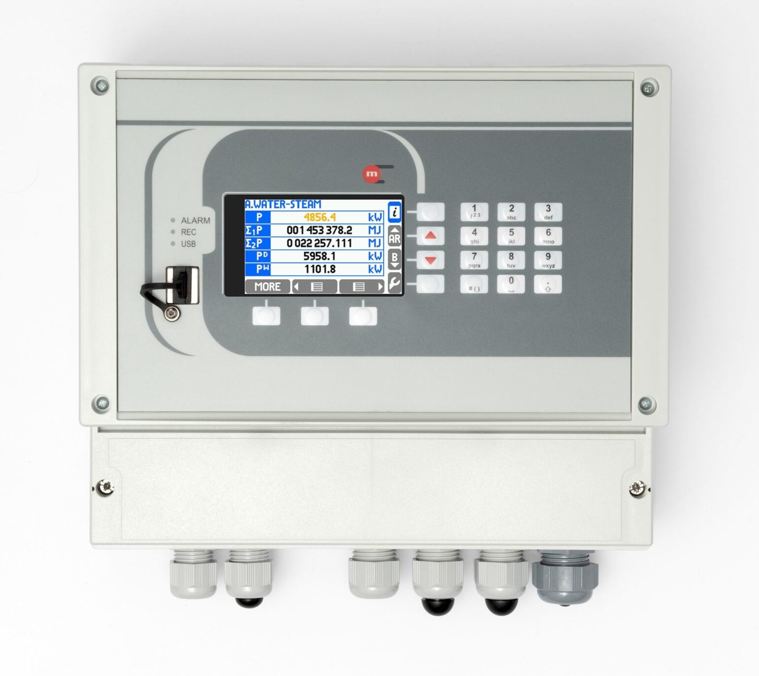
Flow computer for calculating compensated flow and thermal energy of steam, water and other liquid media and compensated flow of process gases with electronically registered results in wall-mounted case. The computer communicates with RS‑485 / Modbus RTU and HART transducers.

Flow computer
• Simultaneous consumption calculations in up to two different measurement systems (A, B) for separate process lines
• Balancing flows – sum, difference, comparison
• 5 channels for digital data readout
• 2 PULS type inputs
• Alarm and control functions: 4 alarm and control thresholds for each measurement channel
• 4 semiconducting output relays: alarm and control functions, operation in pulse output mode with fixed pulse weight
• Optional 4-20mA analog output. Advanced recording function allows storage of measurement results. USB port for transferring data from and to the computer
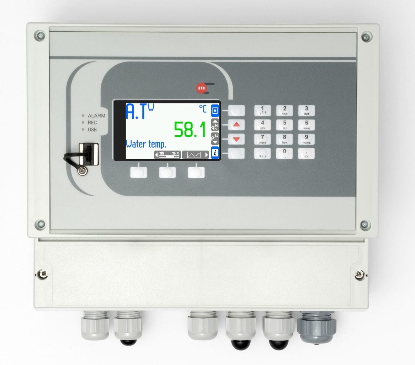
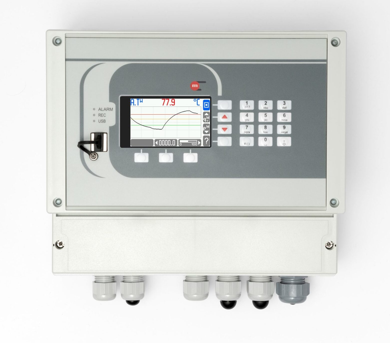
• Color graphic LCD TFT display
• USB port on front panel
• Ethernet port (Modbus TCP protocol, server www)
• RS-485 port (Modbus RTU protocol)
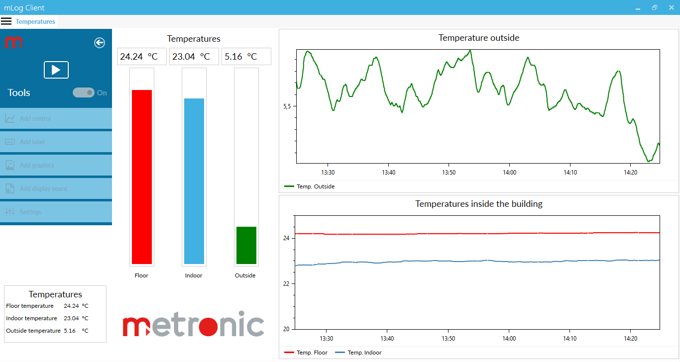
• Software for visualization of measurement results
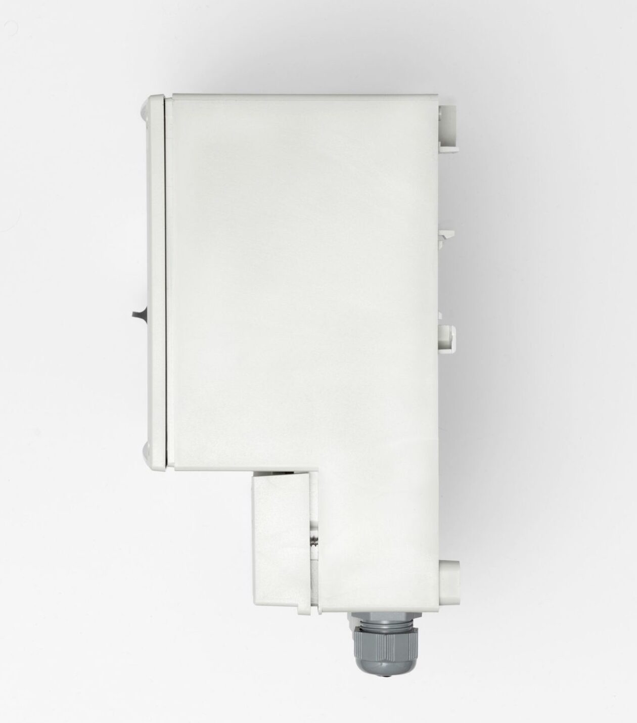
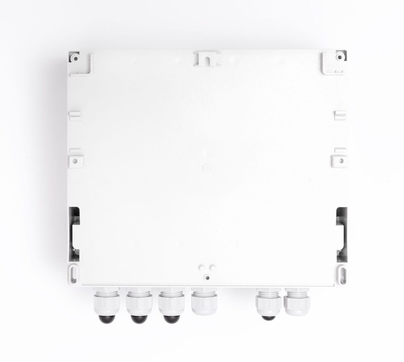
• Wall-mounted case
• 19-buttons extended keyboard version (makes it easier to enter and edit numbers, text, formulas and passwords)
• Powered with 230V or 24 V
Version
Available in two versions
• Basic – implementation of one settlement system
• Extended – implementation of up to three settlement systems A, B
Applications for steam, liquids and technical gases
Process values and calculations relevant to a single installation application are grouped in one system named main application. FP-3021 flow computer can handle up to two independent main applications A or B. Configuration wizard helps to setup one of possible applications
• The flow and heat of a liquid medium
• The flow and delta heat of a liquid medium in a closed supply-return installation
• The flow and delta heat of a liquid medium in an installation with different supply and return flow rates
• The flow and heat of a steam
• The flow and delta heat in a closed steam-condensate installation
• The flow and delta heat in a steam-condensate installation with different steam and condensate flow rates
• The flow and delta heat in a steam-generating installation with the supplied water flow rate measured
• The flow of a gas
Flow rate measurement
• Mass flowmeters
• Volume flowmeters
• Differential pressure devices (orifices and nozzles) according to iteration algorithm according to PN-EN ISO 5167 standard (only for water and steam)
Measurement channels
• 5 channels intended for data readout from Modbus RTU protocol devices and transducers and HART protocol transducers
• Two channels intended for interaction with PULS-type inputs (measurement of frequencies within the range of 0.001Hz … 10kHz, pulse counting, tracking and recording the shorting / disconnecting binary signal)
HART
• Readout of digital quantities from transducers / devices connected in parallel to a current loop
• Operation as Primary Master or Secondary Master
• Readout of variables: PV – primary variable, SV – secondary variable, TV – third variable, FV – fourth variable
MODBUS RTU
• Devices / transducers connected in parallel to one pair of wires (of an RS-485(1) port)
• Transmission rate between 1200bps and 115,200bps
• Readout functions: 03 (Read Holding Register) and 04 (Read Input Register)
• Supported formats of variables: Uns. Integer, Integer, Uns. Long, Uns. Long(sw), Long, Long(sw), Float, Float(sw)
Measurements and additional calculations
• Math functions to perform calculations on measured quantities (eg Sum of flows and power in two pipelines, etc.)
• 8 additional channels: measurement of additional quantities or calculations
• Additional quantities are omitted when performing calculations related to the flow measurement system
• Calculated quantities may serve as auxiliary values or be used directly in measurement systems
Recording measurement results
• Recording to internal 2GB memory
• Checksum secured files – protection against result errors
• Recording frequency for main archive between 3s and 24h; define two recording frequencies, toggled upon exceeding the set alarm thresholds
• Registration of counters, average, minimum and maximum values every 1 hour
Other functions
• Ability to measure, display and record additional values not related to settlement systems (eg condensate level in the tank)
• Algorithm of overshooting of the ordered power and of the excess energy meter with the possibility of registration saturation of superheated steam
• Advanced user and password system
• 1 optional 4-20mA analog output
• Available also in panel case – FP-3021
Application
The FP-30×1(N) series flow computers are used in many industries: power plants, CHPs, metallurgical, food, chemical, wood and paper industries, etc. Example of application: calculating the amount of energy produced at the power plant; measurement of the flow and energy of steam used in the food industry for production purposes (pasteurization of processed products).
This product is CE marked.
Declarations of Conformity are available on request.
| COMPENSATED FLOW AND HEAT ENERGY MEASUREMENT | ||
| Accuracy of compensated steam, water, other liquid or technical gas flow | <2% (typically <0.5%) | |
| Frequency of measurement and calculation results | 1 s | |
| FRONT PANEL | ||
| Display type | LCD TFT colour 272×480 px | |
| Display size | 43.8 mm x 77.4 mm | |
| Keyboard | · FP-3021: 7 membrane buttons
· FP-3021N: 19 membrane buttons |
|
| LED indication | 3 LEDs 3-colour, red-orange-green | |
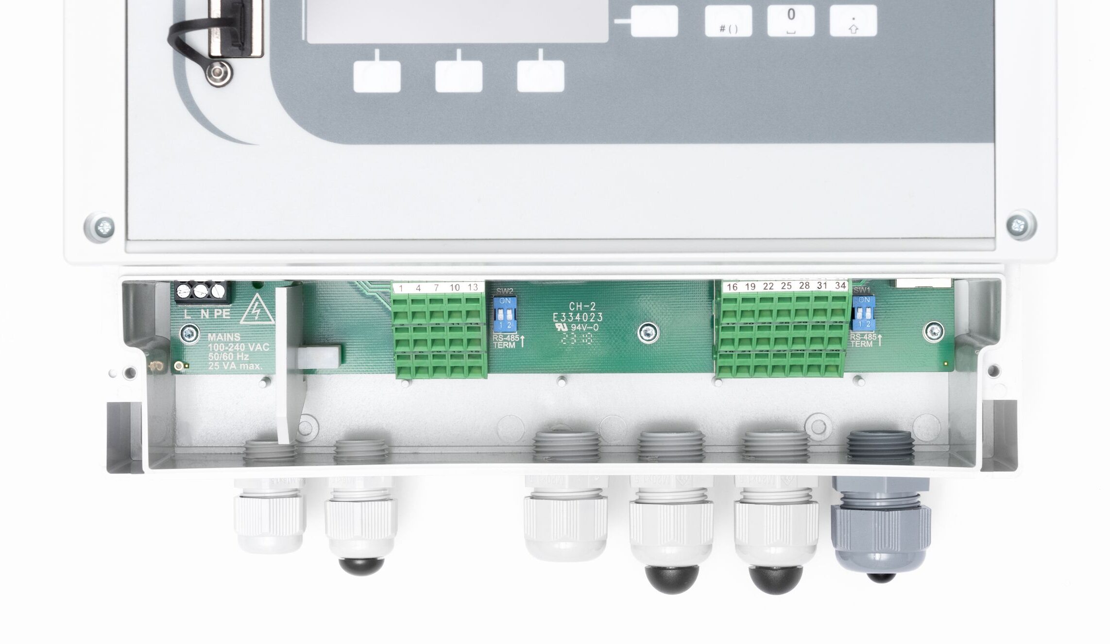
| INPUTS ORGANIZATION | ||
| FP-3021, FP-3021N |
HART port: RS-485 (1) port: 2 x PULS: IN6, IN7 |
|
| HART port | ||
| Transmission protocol | Master type 0 or 1, rev. 4, rev. 5, rev. 6; FSK | |
| Implemented features | Reading variables PV, SV, TV, FV
Retrieve long address (rev. 5, rev. 6) Change of short address |
|
| Multidrop mode | Yes, up to 12 devices | |
| Loop power | 24 VDC (max 50 mA) | |
| Analog line 4-20mA reading | No | |
| Galvanic isolation from supply voltage | 400 VAC (functional isolation) | |
| RS-485 (1) serial port – Master | ||
| Transmission protocol | Modbus RTU | |
| Data format | Uns. Integer, Integer, Uns. Long, Uns. Long (sw), Long, Long (sw), Float, Float (sw) | |
| Frequency of reading | 3 s, 4 s, 5 s, 6 s, 10 s, 12 s, 15 s, 30 s, 1 min | |
| Baud rate | 1.2, 2.4, 4.8, 9.6, 19.2, 38.4, 57.6, 115.2 kbps | |
| Address space of transducers | 1 .. 247 | |
| Maximum load | 32 receivers/transmitters | |
| Maximum line length | 1200 m | |
| Maximum differential voltage A(+) – B(-) | -7 .. +12 V | |
| Maximum total voltage A(+) – ‘ground’ or B(-) – ‘ground’ |
-7 .. +12 V | |
| Minimal output signal from transmitter | 1.5 V (for R0 = 54 Ω) | |
| Minimum receiver sensitivity | 200 mV / RIN = 12 kΩ | |
| Minimum impedance of data transmission line | 54 Ω | |
| Internal terminating resistor | Yes, activated by short-circuit pins on terminal block | |
| Short-circuit/thermal protection | Yes/Yes | |
| Galvanic isolation from supply voltage | 400 VAC (functional isolation) | |
| PULS type inputs (binary/pulse/frequency) | ||
| Maximum input voltage | ±28 VDC | |
| Galvanic isolation from supply voltage | 400 VAC (functional isolation) | |
| Functions | State detection
Pulse counting Frequency measurement |
|
| Measuring range | 0.001 Hz .. 10 kHz
(0.001 Hz .. 1 kHz with filtrating capacitor) |
|
| Minimum impulse width | 20 ms
0.5 ms with filtrating capacitor |
|
| Accuracy (at Ta = +20 °C) | 0.02% | |
| Configuration: OC/contact(1) | ||
| Open circuit voltage | 12 V | |
| Short circuit current | 12 mA | |
| On/off threshold | 2.7 V / 2.4 V | |
| (1)The default setting. | ||
| Configuration: voltage input | ||
| Input resistance | >10 kW | |
| On/off threshold | 2.7 V / 2.4 V | |
| Open circuit voltage | 12 V | |
| Configuration: Namur | ||
| High impedance state | 0.4 .. 1 mA | |
| Low impedance state | 2.2 .. 6.5 mA | |
| 4-20mA analogue output (optional) | ||
| Output signal | 4-20mA (3.6–22 mA) | |
| Maximum voltage between I+ and I- | 28 VDC | |
| Loop resistance (at Ucc = 24 V) | 0 .. 500 Ω | |
| Converter resolution D/A | 16 bits | |
| Accuracy | 0.5% | |
| Current loop supply | External or internal power supply 24 VDC /22 mA | |
| Galvanic isolation from supply voltage | 400 VAC (functional isolation) | |
| Binary outputs (Solid State Relays) | ||
| Number of outputs | 4 | |
| Type of outputs | Solid State Relays | |
| Maximum load current | 100 mA DC/AC | |
| Maximum voltage | 60 V DC/AC | |
| Galvanic isolation between outputs | 400 VAC (functional isolation) | |
| Galvanic isolation from supply voltage | 400 VAC (functional isolation) | |
| RS-485 (2) serial port – Slave | ||
| Maximum load | 32 receivers/transmitters | |
| Maximum line length | 1200 m | |
| Maximum differential voltage A(+) – B(-) | -7 .. +12 V | |
| Maximum total voltage A(+) – ‘ground’ or B(-) – ‘ground’ |
-7 .. +12 V | |
| Minimal output signal from transmitter | 1.5 V (for R0 = 54 W) | |
| Minimum receiver sensitivity | 200 mV / RIN = 12 kW | |
| Minimum impedance of data transmission line | 54 W | |
| Internal terminating resistor | Yes, activated by short-circuit pins on terminal block | |
| Short-circuit/thermal protection | Yes/Yes | |
| Transmission protocol | ASCII
Modbus RTU |
|
| Baud rate | 2.4, 4.8, 9.6 ,19.2, 38.4, 57.6, 115.2 kbps | |
| Parity control | Even, Odd, None | |
| Frame | 1 start bit, 8 data bits, 1 stop bit | |
| Galvanic isolation | No | |
| Ethernet port | ||
| Transmission protocol | Modbus TCP, ICMP (ping), DHCP server, http server | |
| Interface | 10BaseT Ethernet | |
| Data buffer | 300 B | |
| Number of opened connections (simultaneously) | 4 | |
| Connector type | RJ-45 | |
| LED signaling | 2, build in RJ-45 socked | |
| USB port | ||
| Socket type | A type, according to USB standard | |
| Version | USB 1.1 | |
| Socket protection class | IP54 | |
| Recording format | FAT16 (within a limited scope) | |
| Recording indication | red-orange-green LED on the front panel | |
| FP-3021 power supply | ||
| Supply voltage | 24 VAC (+5%/-10%) or 24 VDC (15 .. 30 VDC) | |
| Maximum power consumption | 5 VA / 5 W | |
| FP-3021N power supply | ||
| Supply voltage | 100 .. 240 VAC 50/60 Hz
or 24 VAC (+5%/-10%) or 24 VDC (15 .. 30 VDC) |
|
| Maximum power consumption | 14 VA / 14 W (for 100 .. 240 VAC power supply)
5 VA / 5 W (for 24 VAC/VDC power supply) |
|
| Wire terminals | ||
| Type | · FP-3021: screw type terminal blocks
· FP-3021N: spring type terminal block |
|
| Conductor cross section | · FP-3021: solid max. 1.5 mm2
· FP-3021N: stranded 0.2 .. 1.5 mm2 |
|
| FP-3021 enclosure – dimensions | ||
| Enclosure type | Panel mount, nonflammable plastic material ‘Noryl’ | |
| Dimensions (width x height x depth) | 144 mm x 72 mm x 130 mm | |
| Enclosure depth with terminals | ca. 140 mm | |
| Panel cut-out dimensions (width x height) | 138+1.0 mm X 68+0.7 mm | |
| Panel maximum thickness | 5 mm | |
| Weight | ca. 0.5 kg | |
| Protection class from the front panel | IP54 | |
| Protection class from the rear panel | IP30 | |
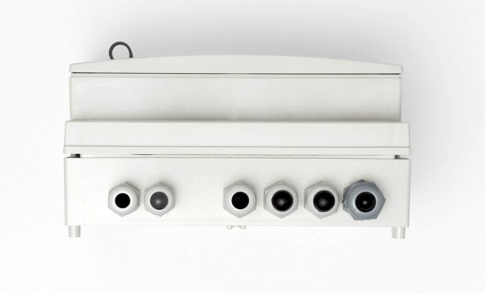
| FP-3021N enclosure – dimensions | ||
| Enclosure type | Wall mount, PC material | |
| Dimensions (width x height x depth) | 257 mm X 217 mm X 125 mm (without cable glands)
257 mm X 247 mm X 125 mm (with cable glands) |
|
| Weight | ok. 2.1 kg | |
| Protection class | IP54 | |
| Environmental conditions | ||
| Ambient temperature | · FP-3021: 0 .. +50 °C
· FP-3021N: -20 .. +50 °C |
|
| Relative humidity | 0 .. 75% (without steam condensation) | |
| Storage temperature | -20 .. +80 °C | |
| Overvoltage category | OV II | |
| Pollution degree | PD 2 | |
| LVD (safety) | EN 61010-1 | |
| EMC | Directive 2014/30/EU:
· immunity for industrial environments according to EN 61326-1:2013 (Table 2) · conductive and radiated emissions Class A equipment according to EN 61326-1:2013 |
|
| RoHS | Directive 2011/65/EU | |
| Installation location | · FP-3021: Indoor only
· FP-3021N: Indoor or outdoor(2) |
|
| (2)If additional protection against atmospheric precipitation is provided (roofing), the device can be installed outdoor. | ||


Flow computer
• Simultaneous consumption calculations in up to two different measurement systems (A, B) for separate process lines
• Balancing flows – sum, difference, comparison
• 5 channels for digital data readout
• 2 PULS type inputs
• Alarm and control functions: 4 alarm and control thresholds for each measurement channel
• 4 semiconducting output relays: alarm and control functions, operation in pulse output mode with fixed pulse weight
• Optional 4-20mA analog output. Advanced recording function allows storage of measurement results. USB port for transferring data from and to the computer
• Color graphic LCD TFT display
• USB port on front panel
• Ethernet port (Modbus TCP protocol, server www)
• RS-485 port (Modbus RTU protocol)
• Software for visualization of measurement results
• Wall-mounted case
• 19-buttons extended keyboard version (makes it easier to enter and edit numbers, text, formulas and passwords)
• Powered with 230V or 24 V
Version
Available in two versions
• Basic – implementation of one settlement system
• Extended – implementation of up to three settlement systems A, B
Applications for steam, liquids and technical gases
Process values and calculations relevant to a single installation application are grouped in one system named main application. FP-3021 flow computer can handle up to two independent main applications A or B. Configuration wizard helps to setup one of possible applications
• The flow and heat of a liquid medium
• The flow and delta heat of a liquid medium in a closed supply-return installation
• The flow and delta heat of a liquid medium in an installation with different supply and return flow rates
• The flow and heat of a steam
• The flow and delta heat in a closed steam-condensate installation
• The flow and delta heat in a steam-condensate installation with different steam and condensate flow rates
• The flow and delta heat in a steam-generating installation with the supplied water flow rate measured
• The flow of a gas
Flow rate measurement
• Mass flowmeters
• Volume flowmeters
• Differential pressure devices (orifices and nozzles) according to iteration algorithm according to PN-EN ISO 5167 standard (only for water and steam)
Measurement channels
• 5 channels intended for data readout from Modbus RTU protocol devices and transducers and HART protocol transducers
• Two channels intended for interaction with PULS-type inputs (measurement of frequencies within the range of 0.001Hz … 10kHz, pulse counting, tracking and recording the shorting / disconnecting binary signal)
HART
• Readout of digital quantities from transducers / devices connected in parallel to a current loop
• Operation as Primary Master or Secondary Master
• Readout of variables: PV – primary variable, SV – secondary variable, TV – third variable, FV – fourth variable
MODBUS RTU
• Devices / transducers connected in parallel to one pair of wires (of an RS-485(1) port)
• Transmission rate between 1200bps and 115,200bps
• Readout functions: 03 (Read Holding Register) and 04 (Read Input Register)
• Supported formats of variables: Uns. Integer, Integer, Uns. Long, Uns. Long(sw), Long, Long(sw), Float, Float(sw)
Measurements and additional calculations
• Math functions to perform calculations on measured quantities (eg Sum of flows and power in two pipelines, etc.)
• 8 additional channels: measurement of additional quantities or calculations
• Additional quantities are omitted when performing calculations related to the flow measurement system
• Calculated quantities may serve as auxiliary values or be used directly in measurement systems
Recording measurement results
• Recording to internal 2GB memory
• Checksum secured files – protection against result errors
• Recording frequency for main archive between 3s and 24h; define two recording frequencies, toggled upon exceeding the set alarm thresholds
• Registration of counters, average, minimum and maximum values every 1 hour
Other functions
• Ability to measure, display and record additional values not related to settlement systems (eg condensate level in the tank)
• Algorithm of overshooting of the ordered power and of the excess energy meter with the possibility of registration saturation of superheated steam
• Advanced user and password system
• 1 optional 4-20mA analog output
• Available also in panel case – FP-3021
Application
The FP-30×1(N) series flow computers are used in many industries: power plants, CHPs, metallurgical, food, chemical, wood and paper industries, etc. Example of application: calculating the amount of energy produced at the power plant; measurement of the flow and energy of steam used in the food industry for production purposes (pasteurization of processed products).
This product is CE marked.
Declarations of Conformity are available on request.
| COMPENSATED FLOW AND HEAT ENERGY MEASUREMENT | ||
| Accuracy of compensated steam, water, other liquid or technical gas flow | <2% (typically <0.5%) | |
| Frequency of measurement and calculation results | 1 s | |
| FRONT PANEL | ||
| Display type | LCD TFT colour 272×480 px | |
| Display size | 43.8 mm x 77.4 mm | |
| Keyboard | · FP-3021: 7 membrane buttons
· FP-3021N: 19 membrane buttons |
|
| LED indication | 3 LEDs 3-colour, red-orange-green | |
| INPUTS ORGANIZATION | ||
| FP-3021, FP-3021N |
HART port: RS-485 (1) port: 2 x PULS: IN6, IN7 |
|
| HART port | ||
| Transmission protocol | Master type 0 or 1, rev. 4, rev. 5, rev. 6; FSK | |
| Implemented features | Reading variables PV, SV, TV, FV
Retrieve long address (rev. 5, rev. 6) Change of short address |
|
| Multidrop mode | Yes, up to 12 devices | |
| Loop power | 24 VDC (max 50 mA) | |
| Analog line 4-20mA reading | No | |
| Galvanic isolation from supply voltage | 400 VAC (functional isolation) | |
| RS-485 (1) serial port – Master | ||
| Transmission protocol | Modbus RTU | |
| Data format | Uns. Integer, Integer, Uns. Long, Uns. Long (sw), Long, Long (sw), Float, Float (sw) | |
| Frequency of reading | 3 s, 4 s, 5 s, 6 s, 10 s, 12 s, 15 s, 30 s, 1 min | |
| Baud rate | 1.2, 2.4, 4.8, 9.6, 19.2, 38.4, 57.6, 115.2 kbps | |
| Address space of transducers | 1 .. 247 | |
| Maximum load | 32 receivers/transmitters | |
| Maximum line length | 1200 m | |
| Maximum differential voltage A(+) – B(-) | -7 .. +12 V | |
| Maximum total voltage A(+) – ‘ground’ or B(-) – ‘ground’ |
-7 .. +12 V | |
| Minimal output signal from transmitter | 1.5 V (for R0 = 54 Ω) | |
| Minimum receiver sensitivity | 200 mV / RIN = 12 kΩ | |
| Minimum impedance of data transmission line | 54 Ω | |
| Internal terminating resistor | Yes, activated by short-circuit pins on terminal block | |
| Short-circuit/thermal protection | Yes/Yes | |
| Galvanic isolation from supply voltage | 400 VAC (functional isolation) | |
| PULS type inputs (binary/pulse/frequency) | ||
| Maximum input voltage | ±28 VDC | |
| Galvanic isolation from supply voltage | 400 VAC (functional isolation) | |
| Functions | State detection
Pulse counting Frequency measurement |
|
| Measuring range | 0.001 Hz .. 10 kHz
(0.001 Hz .. 1 kHz with filtrating capacitor) |
|
| Minimum impulse width | 20 ms
0.5 ms with filtrating capacitor |
|
| Accuracy (at Ta = +20 °C) | 0.02% | |
| Configuration: OC/contact(1) | ||
| Open circuit voltage | 12 V | |
| Short circuit current | 12 mA | |
| On/off threshold | 2.7 V / 2.4 V | |
| (1)The default setting. | ||
| Configuration: voltage input | ||
| Input resistance | >10 kW | |
| On/off threshold | 2.7 V / 2.4 V | |
| Open circuit voltage | 12 V | |
| Configuration: Namur | ||
| High impedance state | 0.4 .. 1 mA | |
| Low impedance state | 2.2 .. 6.5 mA | |
| 4-20mA analogue output (optional) | ||
| Output signal | 4-20mA (3.6–22 mA) | |
| Maximum voltage between I+ and I- | 28 VDC | |
| Loop resistance (at Ucc = 24 V) | 0 .. 500 Ω | |
| Converter resolution D/A | 16 bits | |
| Accuracy | 0.5% | |
| Current loop supply | External or internal power supply 24 VDC /22 mA | |
| Galvanic isolation from supply voltage | 400 VAC (functional isolation) | |
| Binary outputs (Solid State Relays) | ||
| Number of outputs | 4 | |
| Type of outputs | Solid State Relays | |
| Maximum load current | 100 mA DC/AC | |
| Maximum voltage | 60 V DC/AC | |
| Galvanic isolation between outputs | 400 VAC (functional isolation) | |
| Galvanic isolation from supply voltage | 400 VAC (functional isolation) | |
| RS-485 (2) serial port – Slave | ||
| Maximum load | 32 receivers/transmitters | |
| Maximum line length | 1200 m | |
| Maximum differential voltage A(+) – B(-) | -7 .. +12 V | |
| Maximum total voltage A(+) – ‘ground’ or B(-) – ‘ground’ |
-7 .. +12 V | |
| Minimal output signal from transmitter | 1.5 V (for R0 = 54 W) | |
| Minimum receiver sensitivity | 200 mV / RIN = 12 kW | |
| Minimum impedance of data transmission line | 54 W | |
| Internal terminating resistor | Yes, activated by short-circuit pins on terminal block | |
| Short-circuit/thermal protection | Yes/Yes | |
| Transmission protocol | ASCII
Modbus RTU |
|
| Baud rate | 2.4, 4.8, 9.6 ,19.2, 38.4, 57.6, 115.2 kbps | |
| Parity control | Even, Odd, None | |
| Frame | 1 start bit, 8 data bits, 1 stop bit | |
| Galvanic isolation | No | |
| Ethernet port | ||
| Transmission protocol | Modbus TCP, ICMP (ping), DHCP server, http server | |
| Interface | 10BaseT Ethernet | |
| Data buffer | 300 B | |
| Number of opened connections (simultaneously) | 4 | |
| Connector type | RJ-45 | |
| LED signaling | 2, build in RJ-45 socked | |
| USB port | ||
| Socket type | A type, according to USB standard | |
| Version | USB 1.1 | |
| Socket protection class | IP54 | |
| Recording format | FAT16 (within a limited scope) | |
| Recording indication | red-orange-green LED on the front panel | |
| FP-3021 power supply | ||
| Supply voltage | 24 VAC (+5%/-10%) or 24 VDC (15 .. 30 VDC) | |
| Maximum power consumption | 5 VA / 5 W | |
| FP-3021N power supply | ||
| Supply voltage | 100 .. 240 VAC 50/60 Hz
or 24 VAC (+5%/-10%) or 24 VDC (15 .. 30 VDC) |
|
| Maximum power consumption | 14 VA / 14 W (for 100 .. 240 VAC power supply)
5 VA / 5 W (for 24 VAC/VDC power supply) |
|
| Wire terminals | ||
| Type | · FP-3021: screw type terminal blocks
· FP-3021N: spring type terminal block |
|
| Conductor cross section | · FP-3021: solid max. 1.5 mm2
· FP-3021N: stranded 0.2 .. 1.5 mm2 |
|
| FP-3021 enclosure – dimensions | ||
| Enclosure type | Panel mount, nonflammable plastic material ‘Noryl’ | |
| Dimensions (width x height x depth) | 144 mm x 72 mm x 130 mm | |
| Enclosure depth with terminals | ca. 140 mm | |
| Panel cut-out dimensions (width x height) | 138+1.0 mm X 68+0.7 mm | |
| Panel maximum thickness | 5 mm | |
| Weight | ca. 0.5 kg | |
| Protection class from the front panel | IP54 | |
| Protection class from the rear panel | IP30 | |
| FP-3021N enclosure – dimensions | ||
| Enclosure type | Wall mount, PC material | |
| Dimensions (width x height x depth) | 257 mm X 217 mm X 125 mm (without cable glands)
257 mm X 247 mm X 125 mm (with cable glands) |
|
| Weight | ok. 2.1 kg | |
| Protection class | IP54 | |
| Environmental conditions | ||
| Ambient temperature | · FP-3021: 0 .. +50 °C
· FP-3021N: -20 .. +50 °C |
|
| Relative humidity | 0 .. 75% (without steam condensation) | |
| Storage temperature | -20 .. +80 °C | |
| Overvoltage category | OV II | |
| Pollution degree | PD 2 | |
| LVD (safety) | EN 61010-1 | |
| EMC | Directive 2014/30/EU:
· immunity for industrial environments according to EN 61326-1:2013 (Table 2) · conductive and radiated emissions Class A equipment according to EN 61326-1:2013 |
|
| RoHS | Directive 2011/65/EU | |
| Installation location | · FP-3021: Indoor only
· FP-3021N: Indoor or outdoor(2) |
|
| (2)If additional protection against atmospheric precipitation is provided (roofing), the device can be installed outdoor. | ||