
Flow computers
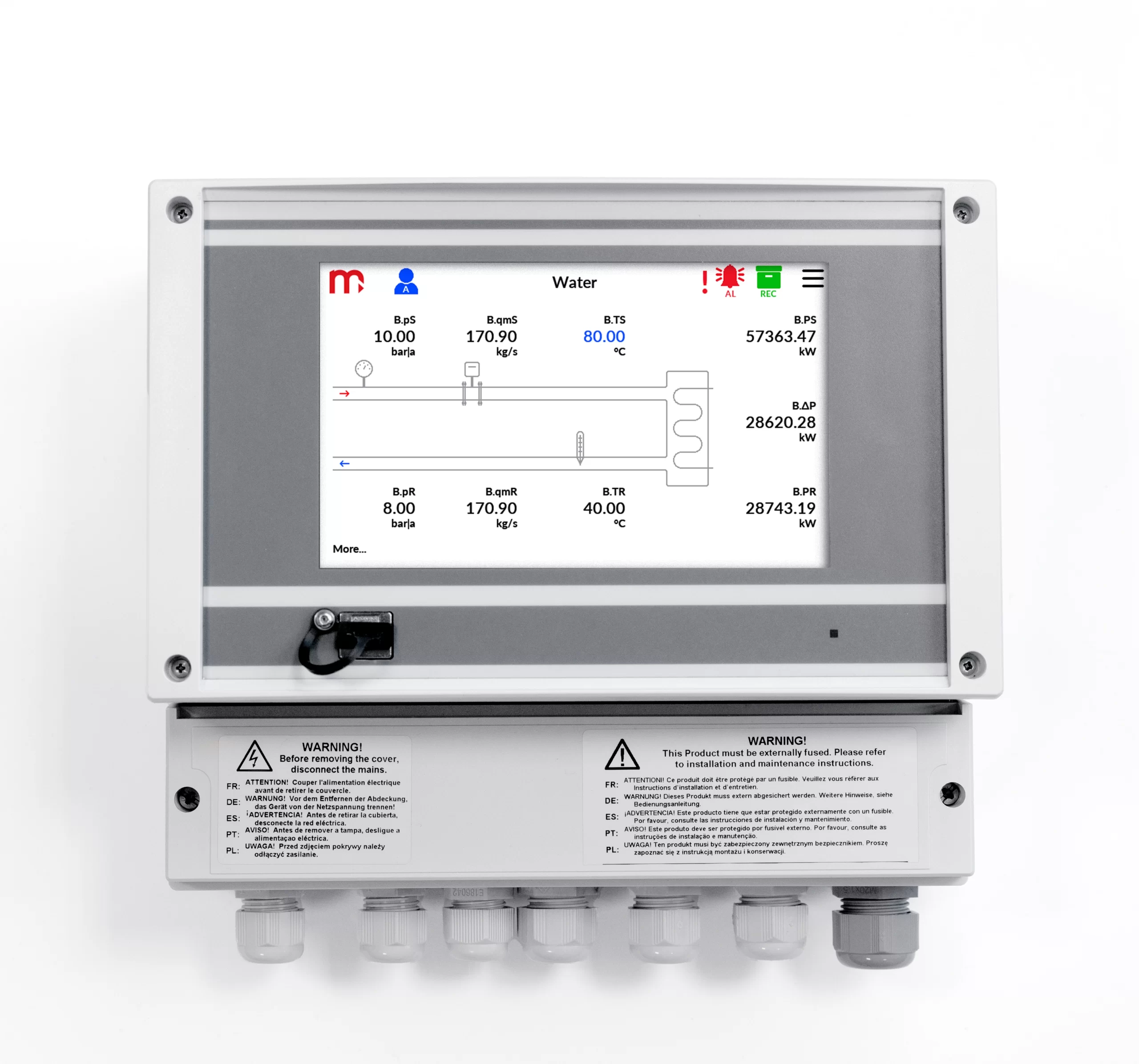
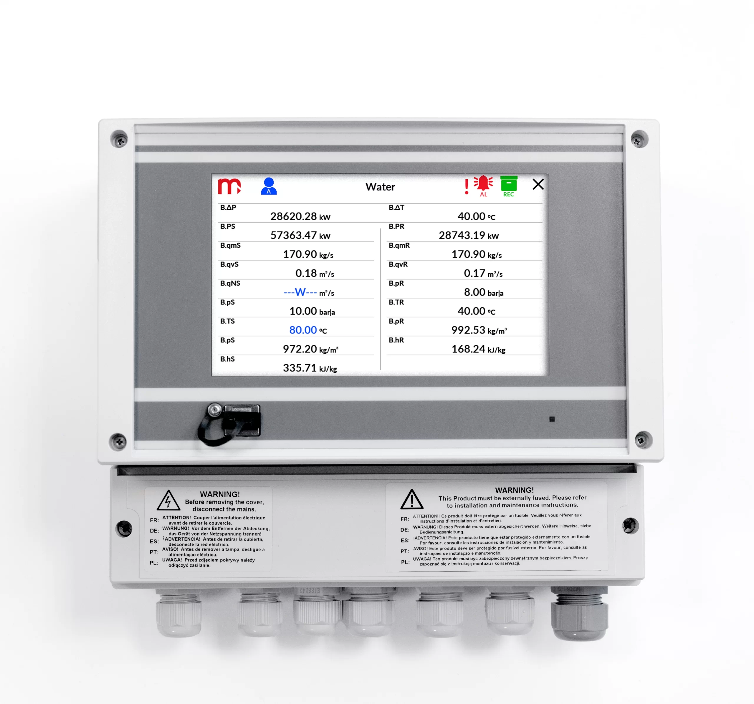
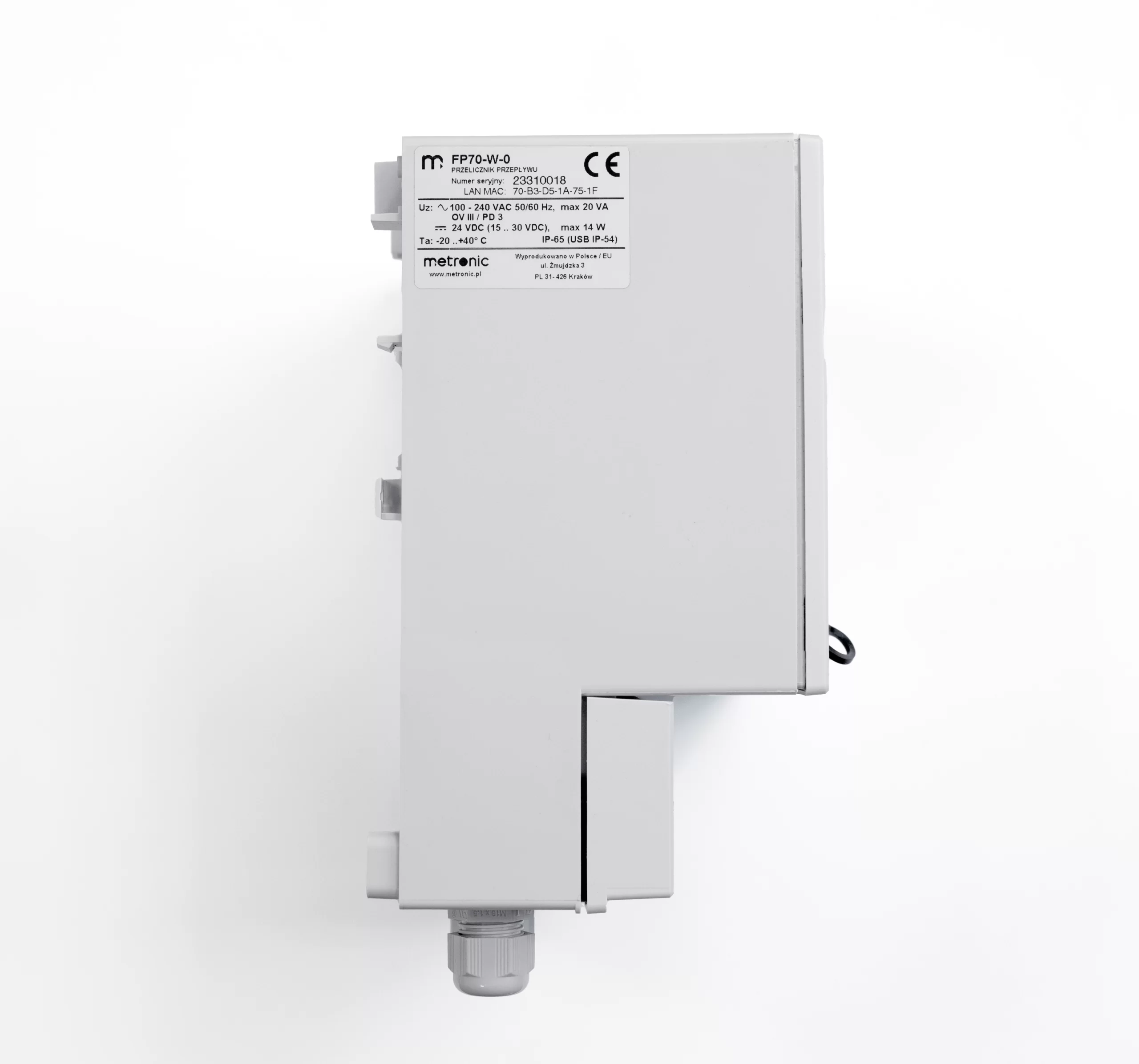
FP70-W
FP70W are versatile and precise flow totalizers used for measurement of steam and water in various industrial installations, measurements of industrial gases and typical or special liquids (like glycol, supercooled water, oils) in heat exchange systems. There is possibility of local alarming or simple control implementation. Data are recorded and can be read locally or periodically using a USB mass storage device.
Device can communicate with master system via Ethernet port (Modbus TCP protocol, www server) or via RS-485 port (Modbus RTU protocol) and can work in distributed control systems.
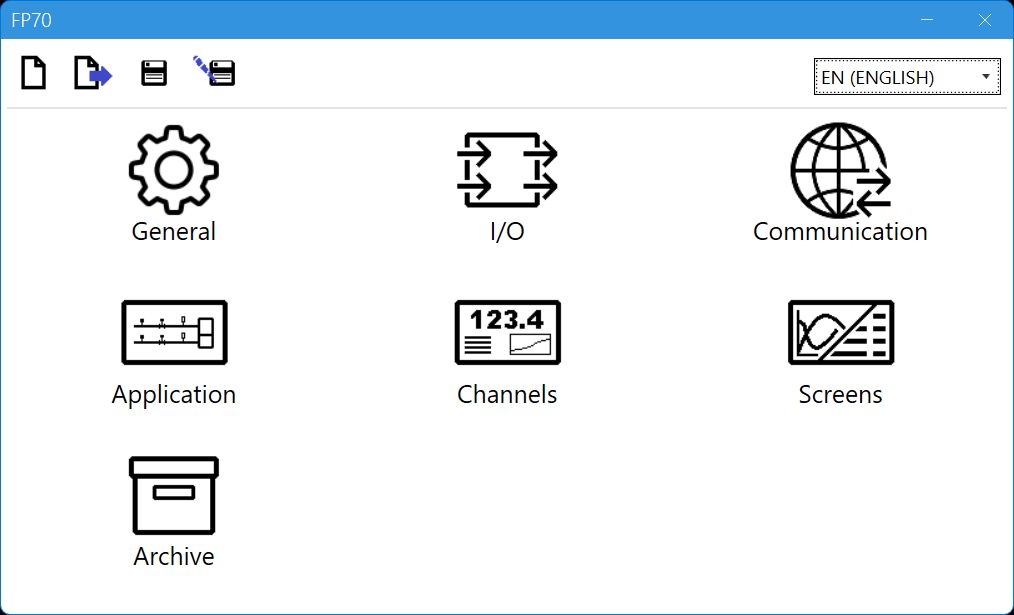
Device may be configured by the user from the front panel or using commissioning software on PC.


Flow computer
- Up to 2 independent installations (A, B )
- Flows and energy balance calculations (systems X )
- 10 measurement inputs
- Math channels & functions (+, -, /, *, √)
- Alarm & control functions, 4 solid state relays (SSR)
- 4-20mA analogue output – one or two (option)
- Advanced data logging, recording data to the text files, 2 GB internal data memory
- User configurable data presentation, the colour TFT display
- RS-485 port (Modbus RTU)
- Ethernet port (Modbus TCP, www server)
- USB port on the front panel
- GSM module (option)
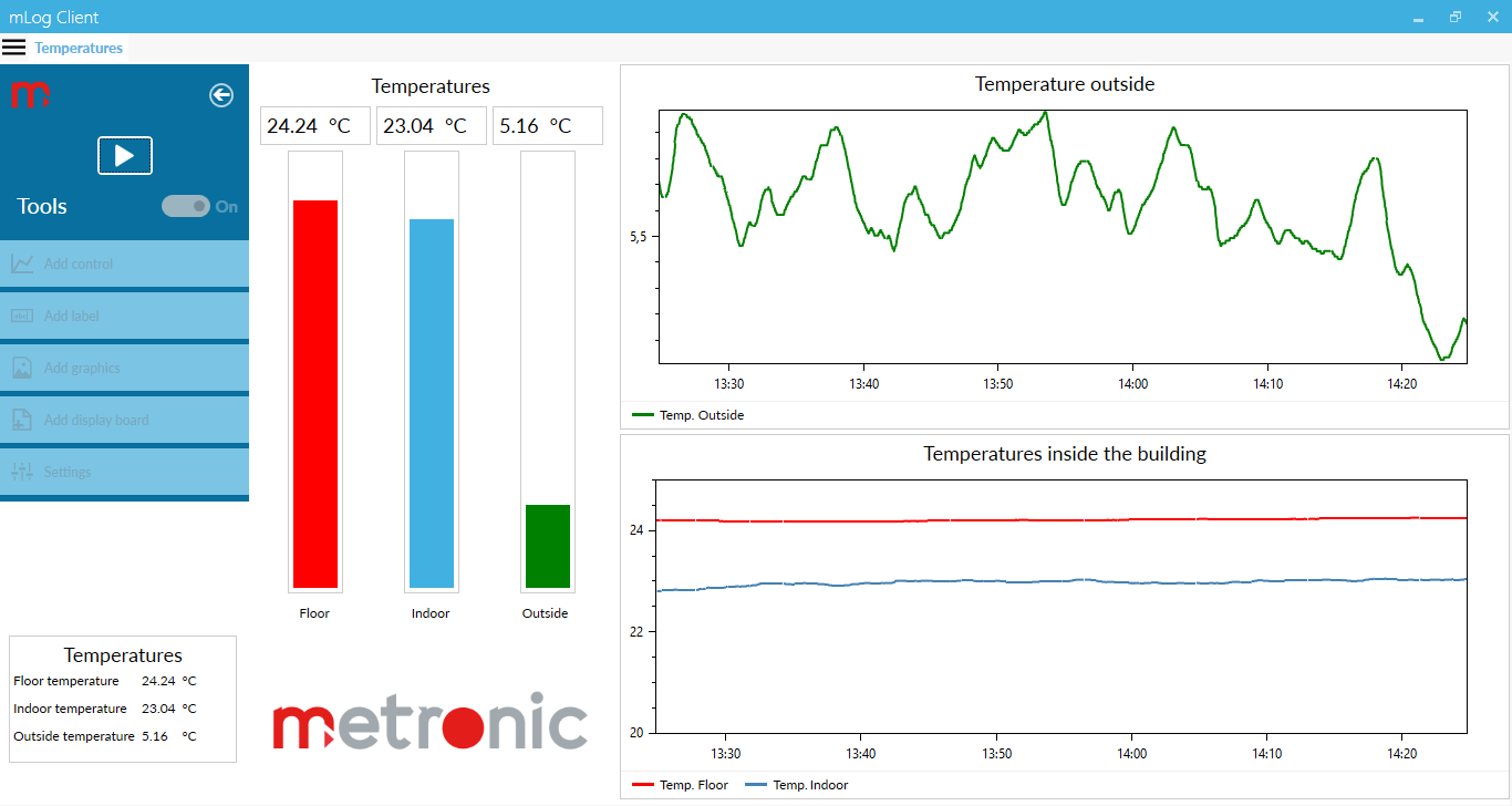
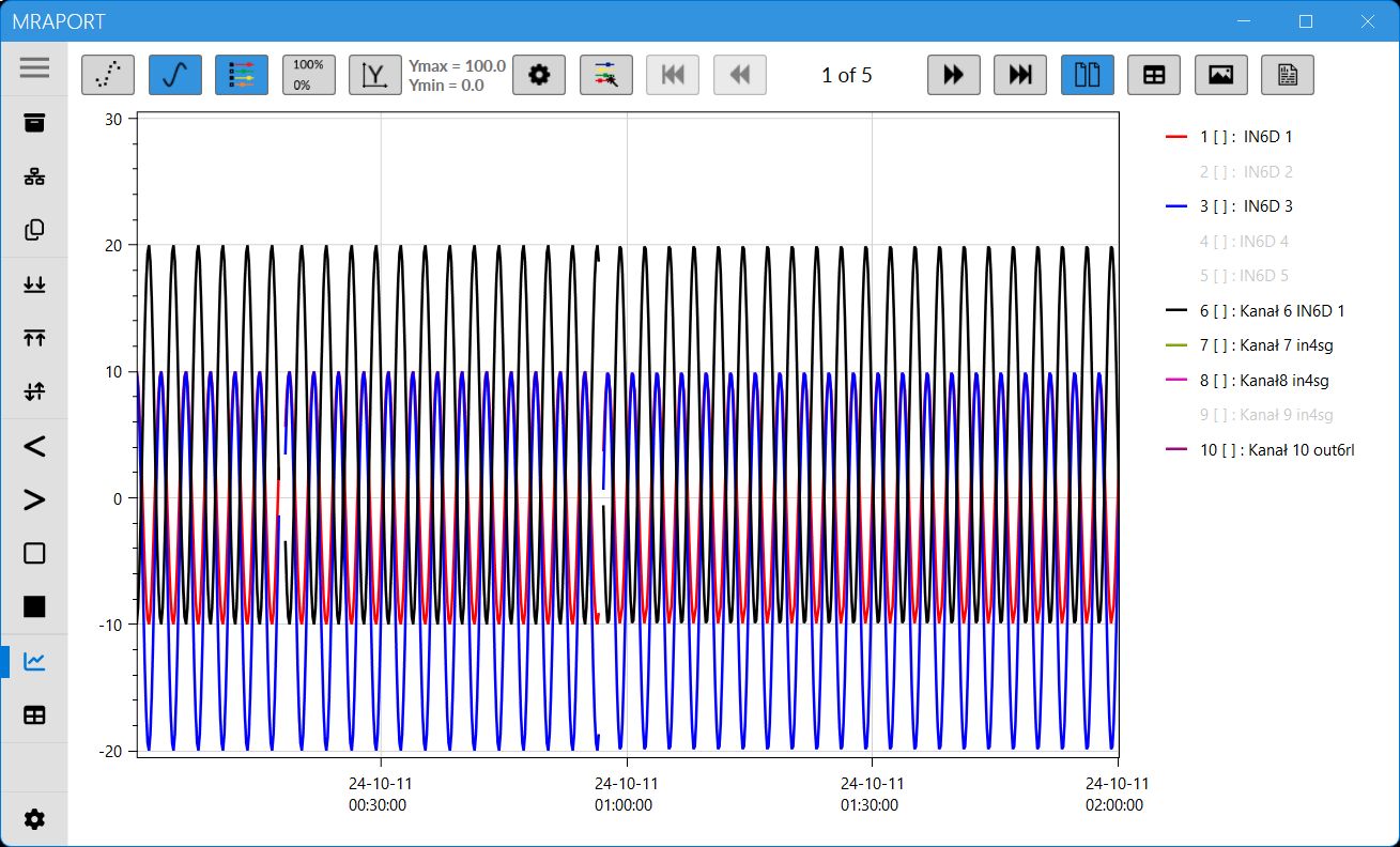
- Dedicated PC software for commissioning and archive data visualization
- Available languages: EN, DE, ES, FR, IT, PL, PT
Applications for steam, liquids and technical gases
- For A, B main application setup one of possible applications using a configuration wizard:
- the flow and heat of a liquid medium
- the flow and delta heat of a liquid medium in a closed supply-return installation
- the flow and delta heat of a liquid medium in an installation with different supply and return flow rates
- the flow and heat of a steam
- the flow and heat of steam for steam-condensate conditions
- the flow and delta heat in a closed steam-condensate installation
- the flow and delta heat in a steam-condensate installation with different steam and condensate flow rates
- the flow and delta heat in a steam-generating installation with the supplied water flow rate measured
- the flow and heat of a technical gases
Flow rate measurement
- The flow computer can work with:
- mass flowmeters
- volume flowmeters
- differential pressure devices with approximation by square root curve or differential pressure devices (orifices and nozzles) according to iteration algorithm according to
PN-EN ISO 5167 standard (only for water and steam)
Inputs and channels types
FP70P/FP70W has: 10 analogue inputs, Ethernet port and RS-485 port. In addition, 24 auxiliary channels are available, which can be used as measuring channels or as a math channels. The device enables supplying the current loop for 4-20mA transducers. Up to 10 User’s characteristics can be defined.
- 2 x RTD, two inputs adapted for connection of resistance temperature sensors (Pt100, Pt200, Pt500, Pt1000, Ni100, Ni120, Ni1000, Cu50, Cu53, Cu100, KTY81, KTY83, KTY84)
- 6 x I, six inputs for interaction with 0/4-20mA transducers only,
-
2 x PULS, two inputs intended for connection of transducers with a pulse output (range 0.02 Hz … 12,5 kHz).
Auxiliary channel
- 24 auxiliary channels, measurement of additional quantities or calculation of the formula entered by the user (available mathematical operations: addition, subtraction, multiplication, division, extract the root)
The scope of measurement of steam, water parameters and other media
- The flow and heat measurement of superheated or saturated steam or water are according to IAPWS-IF97 recommendations in the operating range of temperature 0 .. 800 ºC and absolute pressure 0.05 .. 16.52 MPa
- Flow and energy measurements of liquids other than water are performed in the range of tabular values entered by the user – density and enthalpy as function of temperature
- Measurement of technical gas flow according to the ideal gas equation
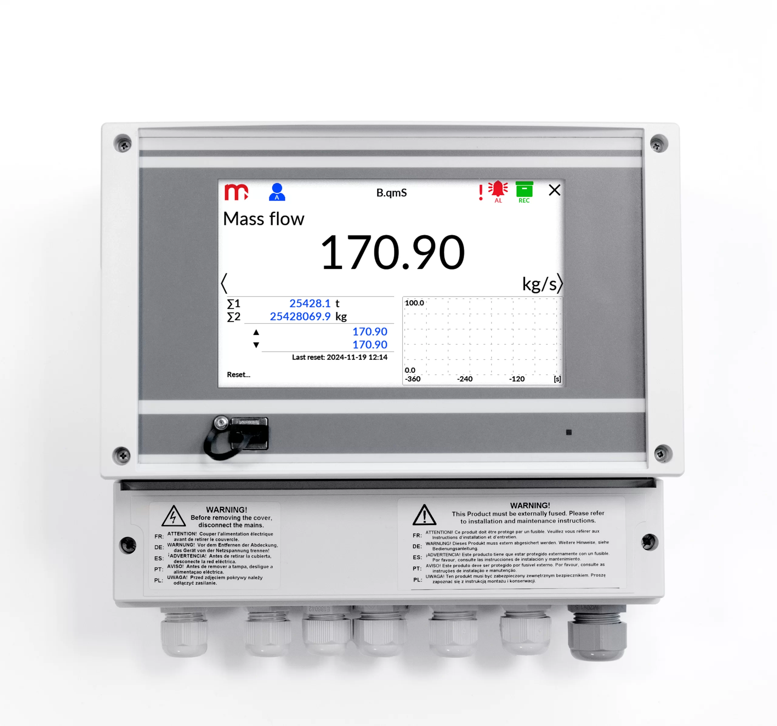
Totalizers
- Totalizers for energy and flow measurements (2 for each channel)
- Totalizers can be reset manually or automatically every day, week or month
- Over and under counters to be realized in additional channels X
Alarms and control
- 2 alarm thresholds for each result
- Alarm or control mode, signaling failure of sensors connected to analogue inputs
- 4 solid state relays rated at 0.1 A/60 V
- E-mail messages about alarm states and cyclical reports with counter values (max. 5 recipients)
Recording measurement results
- Archive files: process values (recording rate from 3 s up to 24 h), totalizers and min/average/max values (record every 1 h and every 24 h)
- Event files: authorization log file, event log file, settings log file (recording after the occurrence of the event)
- 2 recording rates, toggled by alarm state for shorting/opening time of selected binary inputs
- Access to recorded data through USB port on the front panel or through Ethernet port
- Checksum secured files – protection against data manipulation
| COMPENSATED FLOW AND HEAT ENERGY MEASUREMENT | |
| Accuracy of compensated steam, water, other liquid or technical gas flow | <2% (typowo <0,5%) |
| Frequency of measurement and calculation results | 0,5 s |
| FRONT PANEL | |
| Display type FP-70P | 5” LCD TFT colour 800x480px |
| Display type FP-70W | 7” LCD TFT colour 800x480px |
| Display size | 152mm x 91mm |
| LED indication | 3 colour LEDs |
| INPUTS ORGANIZATION | |
| FP70P, FP70W | 2 x PULS: IN1, IN2
2 x RTD: IN3, IN4 6 x I: IN5 – IN10 |
| RTD type analogue inputs | |
| Sensor type | Resistance (according to the table) |
| Measuring range | -200 .. +850 °C dla Pt100
-60 .. +150 °C dla Ni100 -180 ..+200 °C dla Cu100 |
| Sensor connection | 2, 3, or 4-wire |
| Wire resistance compensation | Manual, in range -99.99 .. +99.99 W |
| Maximum resistance of connecting wires | 20 W |
| A/D converter resolution | 24 bit |
| Accuracy (at Ta = +20 °C) | ± 0,5 °C (typowo ± 0,3 °C) |
| Temperature drift | Max ± 0,02 °C / °C |
| Galvanic isolation between inputs | No, common potential GND for all inputs |
| Galvanic isolation from supply voltage | 400 VAC (functional isolation) |
| 0/4-20mA type analogue inputs | |
| Signal type | 0-20mA lub 4-20mA |
| Transmitter connection | Passive (supplied from measuring loop) or active converter) |
| Input resistance | 12 W ±10% ? |
| Transmitters supply | 24 VDC / max 22 mA |
| A/D converter resolution | 24 bit |
| Accuracy (at Ta = +20 °C) | ±0.1% of the range (typically ±0.05% of the range) |
| Temperature drift | Max ±50 ppm / °C |
| Galvanic isolation between inputs | No, common potential GND for all inputs |
| Galvanic isolation from supply voltage | 400 VAC (functional isolation) |
| PULS type inputs (binary/pulse/frequency) | |
| Maximum input voltage | ±28 VDC |
| Galvanic isolation between inputs | No, common potential GND for all inputs |
| Galvanic isolation from supply voltage | 400 VAC (functional isolation) |
| Functions | State detection
Pulse counting Frequency measurement |
| Measuring range | 0,02 Hz do 12,5 kHz |
| Minimum impulse width | 20 ms
0.5 ms with filtrating capacitor |
| Accuracy (at Ta = +20 °C) | 0.02% |
| Configuration: OC/contact(1) | |
| Open circuit voltage | 12 V |
| Short circuit current | 12 mA |
| On/off threshold | 2.7 V / 2.4 V |
| (1)The default setting. | |
| Configuration: voltage input | |
| Input resistance | >10 kW |
| On/off threshold | 2.7 V / 2.4 V |
| Open circuit voltage | 12 V |
| Configuration: Namur | |
| High impedance state | 0.4 .. 1 mA |
| Low impedance state | 2.2 .. 6.5 mA |
| 4-20mA analogue output (optional) | |
| Number of outputs | 1 or 2 |
| Output signal | 4-20mA (3.6–22 mA) |
| Maximum voltage between I+ and I- | 28 VDC |
| Loop resistance (at Ucc = 24 V) | 0 .. 500 Ω |
| Converter resolution D/A | 16 bits |
| Accuracy | 0.5% |
| Current loop supply | External or internal power supply 24 VDC / 22 mA |
| Galvanic isolation between outputs | 400 VAC (functional isolation) |
| Galvanic isolation from supply voltage | 400 VAC (functional isolation) |
| Binary outputs (Solid State Relays) | |
| Number of outputs | 4 |
| Type of outputs | Solid State Relays |
| Maximum load current | 100 mA DC/AC |
| Maximum voltage | 60 V DC/AC |
| Galvanic isolation between outputs | 400 VAC (functional isolation) |
| Galvanic isolation from supply voltage | 400 VAC (functional isolation) |
| RS-485 serial port | |
| Maximum load | 32 receivers/transmitters |
| Maximum line length | 1200 m |
| Maximum differential voltage A(+) – B(-) | -7 .. +12 V |
| Maximum total voltage A(+) – ‘ground’ or B(-) – ‘ground’ |
-7 .. +12 V |
| Minimal output signal from transmitter | 1.5 V (for R0 = 54 W) |
| Minimum receiver sensitivity | 200 mV / RIN = 12 kW |
| Minimum impedance of data transmission line | 54 W |
| Internal terminating resistor | Yes, activated by short-circuit pins on terminal block |
| Short-circuit/thermal protection | Yes/Yes |
| Transmission protocol | Modbus RTU |
| Baud rate | 2.4, 4.8, 9.6 ,19.2, 38.4, 57.6, 115.2 kbps |
| Parity control | Even, Odd, None |
| Frame | 1 start bit, 8 data bits, 1 stop bit |
| Galvanic isolation | No |
| Ethernet port | |
| Transmission protocol | Modbus TCP, ICMP (ping), DHCP server, http server |
| Interface | 10BaseT Ethernet |
| Data buffer | 300 B |
| Number of opened connections (simultaneously) | 4 |
| Connector type | RJ-45 |
| LED signaling | 2, build in RJ-45 socked |
| USB port | |
| Socket type | A type, according to USB standard |
| Version | USB 2.0 |
| Socket protection class | IP54 |
| Recording format | FAT16 (within a limited scope) |
| Recording indication | red-orange-green LED on the front panel |
| FP70P power supply | |
| Supply voltage | 24 VDC (15 .. 30 VDC) |
| Maximum power consumption | 14 VA / 14 W |
| FP70W power supply | |
| Supply voltage | 100 .. 240 VAC 50/60 Hz
24 VDC (15 .. 30 VDC) |
| Maximum power consumption | 28 VA / 28 W (for 100 .. 240 VAC power supply)
14 VA / 14 W (for 24 VAC/VDC power supply) |
| Wire terminals | |
| Type | · FP70P: screw type terminal blocks
· FP70W: spring type terminal block |
| Conductor cross section | · FP70P: solid max. 1.5 mm2
· FP70W: stranded 0.2 .. 1.5 mm2 |
| FP70P enclosure – dimensions | |
| Enclosure type | Panel mount, nonflammable plastic material ‘Noryl’ |
| Dimensions (width x height x depth) | 192 mm x 96 mm x 63.5 mm |
| Enclosure depth with terminals | ca. 72 mm |
| Panel cut-out dimensions (width x height) | 186+1.1 mm x 92+0.6 mm |
| Panel maximum thickness | 5 mm |
| Weight | ca. 0.7 kg |
| Protection class from the front panel | IP54 |
| Protection class from the rear panel | IP30 |
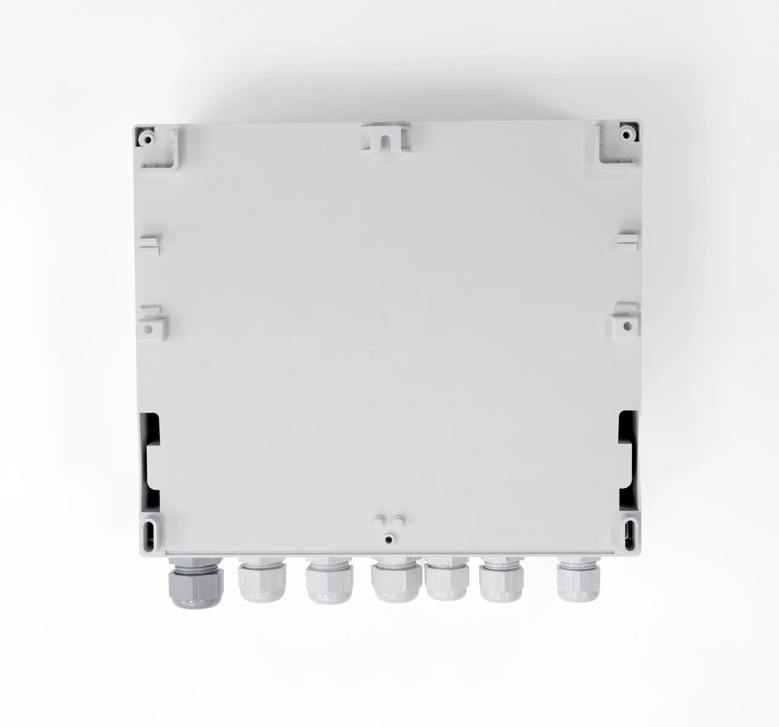
| FP70W enclosure – dimensions | |
| Enclosure type | Wall mount, PC material |
| Dimensions (width x height x depth) | 257 mm x 217 mm x 125 mm (without cable glands)
257 mm x 247 mm x 125 mm (with cable glands) |
| Weight | ca. 2.1 kg |
| Protection class | IP54 |
| FP70P environmental conditions | |
| Ambient temperature | 0 .. +40 °C |
| Relative humidity | 0 .. 75% (without steam condensation) |
| Storage temperature | -20 .. +80 °C |
| Overvoltage category | OV II |
| Pollution degree | PD 2 |
| LVD (safety) | EN 61010-1 |
| EMC | Directive 2014/30/EU:
· immunity for industrial environments according to EN 61326-1:2013 (Table 2) · conductive and radiated emissions Class A equipment according to EN 61326-1:2013 |
| RoHS | Directive 2011/65/EU |
| Installation location | Indoor only |
| FP70W environmental conditions | |
| Ambient temperature | -20 .. +40 °C |
| Relative humidity | 0 .. 75% (without steam condensation) |
| Storage temperature | -20 .. +80 °C |
| Overvoltage category | OV II |
| Pollution degree | PD 2 |
| LVD (safety) | EN 61010-1 |
| EMC | Directive 2014/30/EU:
· immunity for industrial environments according to EN 61326-1:2013 (Table 2) · conductive and radiated emissions Class A equipment according to EN 61326-1:2013 |
| RoHS | Directive 2011/65/EU |
| Installation location | Indoor or outdoor(2) |
| (2)If additional protection against atmospheric precipitation is provided (roofing), the device can be installed outdoor. | |

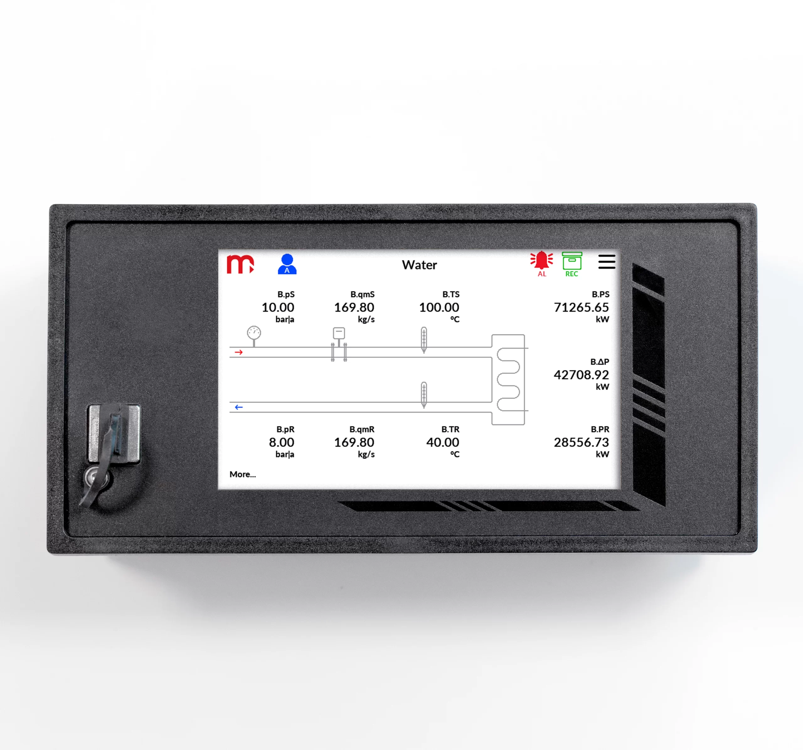


Flow computer
- Up to 2 independent installations (A, B )
- Flows and energy balance calculations (systems X )
- 10 measurement inputs
- Math channels & functions (+, -, /, *, √)
- Alarm & control functions, 4 solid state relays (SSR)
- 4-20mA analogue output – one or two (option)
- Advanced data logging, recording data to the text files, 2 GB internal data memory
- User configurable data presentation, the colour TFT display
- RS-485 port (Modbus RTU)
- Ethernet port (Modbus TCP, www server)
- USB port on the front panel
- GSM module (option)
- Dedicated PC software for commissioning and archive data visualization
- Available languages: EN, DE, ES, FR, IT, PL, PT
Applications for steam, liquids and technical gases
- For A, B main application setup one of possible applications using a configuration wizard:
- the flow and heat of a liquid medium
- the flow and delta heat of a liquid medium in a closed supply-return installation
- the flow and delta heat of a liquid medium in an installation with different supply and return flow rates
- the flow and heat of a steam
- the flow and heat of steam for steam-condensate conditions
- the flow and delta heat in a closed steam-condensate installation
- the flow and delta heat in a steam-condensate installation with different steam and condensate flow rates
- the flow and delta heat in a steam-generating installation with the supplied water flow rate measured
- the flow and heat of a technical gases
Flow rate measurement
- The flow computer can work with:
- mass flowmeters
- volume flowmeters
- differential pressure devices with approximation by square root curve or differential pressure devices (orifices and nozzles) according to iteration algorithm according to
PN-EN ISO 5167 standard (only for water and steam)
Inputs and channels types
FP70P/FP70W has: 10 analogue inputs, Ethernet port and RS-485 port. In addition, 24 auxiliary channels are available, which can be used as measuring channels or as a math channels. The device enables supplying the current loop for 4-20mA transducers. Up to 10 User’s characteristics can be defined.
- 2 x RTD, two inputs adapted for connection of resistance temperature sensors (Pt100, Pt200, Pt500, Pt1000, Ni100, Ni120, Ni1000, Cu50, Cu53, Cu100, KTY81, KTY83, KTY84)
- 6 x I, six inputs for interaction with 0/4-20mA transducers only,
-
2 x PULS, two inputs intended for connection of transducers with a pulse output (range 0.02 Hz … 12,5 kHz).
Auxiliary channel
- 24 auxiliary channels, measurement of additional quantities or calculation of the formula entered by the user (available mathematical operations: addition, subtraction, multiplication, division, extract the root)
The scope of measurement of steam, water parameters and other media
- The flow and heat measurement of superheated or saturated steam or water are according to IAPWS-IF97 recommendations in the operating range of temperature 0 .. 800 ºC and absolute pressure 0.05 .. 16.52 MPa
- Flow and energy measurements of liquids other than water are performed in the range of tabular values entered by the user – density and enthalpy as function of temperature
- Measurement of technical gas flow according to the ideal gas equation
Totalizers
- Totalizers for energy and flow measurements (2 for each channel)
- Totalizers can be reset manually or automatically every day, week or month
- Over and under counters to be realized in additional channels X
Alarms and control
- 2 alarm thresholds for each result
- Alarm or control mode, signaling failure of sensors connected to analogue inputs
- 4 solid state relays rated at 0.1 A/60 V
- E-mail messages about alarm states and cyclical reports with counter values (max. 5 recipients)
Recording measurement results
- Archive files: process values (recording rate from 3 s up to 24 h), totalizers and min/average/max values (record every 1 h and every 24 h)
- Event files: authorization log file, event log file, settings log file (recording after the occurrence of the event)
- 2 recording rates, toggled by alarm state for shorting/opening time of selected binary inputs
- Access to recorded data through USB port on the front panel or through Ethernet port
- Checksum secured files – protection against data manipulation
| COMPENSATED FLOW AND HEAT ENERGY MEASUREMENT | |
| Accuracy of compensated steam, water, other liquid or technical gas flow | <2% (typowo <0,5%) |
| Frequency of measurement and calculation results | 0,5 s |
| FRONT PANEL | |
| Display type FP-70P | 5” LCD TFT colour 800x480px |
| Display type FP-70W | 7” LCD TFT colour 800x480px |
| Display size | 152mm x 91mm |
| LED indication | 3 colour LEDs |
| INPUTS ORGANIZATION | |
| FP70P, FP70W | 2 x PULS: IN1, IN2
2 x RTD: IN3, IN4 6 x I: IN5 – IN10 |
| RTD type analogue inputs | |
| Sensor type | Resistance (according to the table) |
| Measuring range | -200 .. +850 °C dla Pt100
-60 .. +150 °C dla Ni100 -180 ..+200 °C dla Cu100 |
| Sensor connection | 2, 3, or 4-wire |
| Wire resistance compensation | Manual, in range -99.99 .. +99.99 W |
| Maximum resistance of connecting wires | 20 W |
| A/D converter resolution | 24 bit |
| Accuracy (at Ta = +20 °C) | ± 0,5 °C (typowo ± 0,3 °C) |
| Temperature drift | Max ± 0,02 °C / °C |
| Galvanic isolation between inputs | No, common potential GND for all inputs |
| Galvanic isolation from supply voltage | 400 VAC (functional isolation) |
| 0/4-20mA type analogue inputs | |
| Signal type | 0-20mA lub 4-20mA |
| Transmitter connection | Passive (supplied from measuring loop) or active converter) |
| Input resistance | 12 W ±10% ? |
| Transmitters supply | 24 VDC / max 22 mA |
| A/D converter resolution | 24 bit |
| Accuracy (at Ta = +20 °C) | ±0.1% of the range (typically ±0.05% of the range) |
| Temperature drift | Max ±50 ppm / °C |
| Galvanic isolation between inputs | No, common potential GND for all inputs |
| Galvanic isolation from supply voltage | 400 VAC (functional isolation) |
| PULS type inputs (binary/pulse/frequency) | |
| Maximum input voltage | ±28 VDC |
| Galvanic isolation between inputs | No, common potential GND for all inputs |
| Galvanic isolation from supply voltage | 400 VAC (functional isolation) |
| Functions | State detection
Pulse counting Frequency measurement |
| Measuring range | 0,02 Hz do 12,5 kHz |
| Minimum impulse width | 20 ms
0.5 ms with filtrating capacitor |
| Accuracy (at Ta = +20 °C) | 0.02% |
| Configuration: OC/contact(1) | |
| Open circuit voltage | 12 V |
| Short circuit current | 12 mA |
| On/off threshold | 2.7 V / 2.4 V |
| (1)The default setting. | |
| Configuration: voltage input | |
| Input resistance | >10 kW |
| On/off threshold | 2.7 V / 2.4 V |
| Open circuit voltage | 12 V |
| Configuration: Namur | |
| High impedance state | 0.4 .. 1 mA |
| Low impedance state | 2.2 .. 6.5 mA |
| 4-20mA analogue output (optional) | |
| Number of outputs | 1 or 2 |
| Output signal | 4-20mA (3.6–22 mA) |
| Maximum voltage between I+ and I- | 28 VDC |
| Loop resistance (at Ucc = 24 V) | 0 .. 500 Ω |
| Converter resolution D/A | 16 bits |
| Accuracy | 0.5% |
| Current loop supply | External or internal power supply 24 VDC / 22 mA |
| Galvanic isolation between outputs | 400 VAC (functional isolation) |
| Galvanic isolation from supply voltage | 400 VAC (functional isolation) |
| Binary outputs (Solid State Relays) | |
| Number of outputs | 4 |
| Type of outputs | Solid State Relays |
| Maximum load current | 100 mA DC/AC |
| Maximum voltage | 60 V DC/AC |
| Galvanic isolation between outputs | 400 VAC (functional isolation) |
| Galvanic isolation from supply voltage | 400 VAC (functional isolation) |
| RS-485 serial port | |
| Maximum load | 32 receivers/transmitters |
| Maximum line length | 1200 m |
| Maximum differential voltage A(+) – B(-) | -7 .. +12 V |
| Maximum total voltage A(+) – ‘ground’ or B(-) – ‘ground’ |
-7 .. +12 V |
| Minimal output signal from transmitter | 1.5 V (for R0 = 54 W) |
| Minimum receiver sensitivity | 200 mV / RIN = 12 kW |
| Minimum impedance of data transmission line | 54 W |
| Internal terminating resistor | Yes, activated by short-circuit pins on terminal block |
| Short-circuit/thermal protection | Yes/Yes |
| Transmission protocol | Modbus RTU |
| Baud rate | 2.4, 4.8, 9.6 ,19.2, 38.4, 57.6, 115.2 kbps |
| Parity control | Even, Odd, None |
| Frame | 1 start bit, 8 data bits, 1 stop bit |
| Galvanic isolation | No |
| Ethernet port | |
| Transmission protocol | Modbus TCP, ICMP (ping), DHCP server, http server |
| Interface | 10BaseT Ethernet |
| Data buffer | 300 B |
| Number of opened connections (simultaneously) | 4 |
| Connector type | RJ-45 |
| LED signaling | 2, build in RJ-45 socked |
| USB port | |
| Socket type | A type, according to USB standard |
| Version | USB 2.0 |
| Socket protection class | IP54 |
| Recording format | FAT16 (within a limited scope) |
| Recording indication | red-orange-green LED on the front panel |
| FP70P power supply | |
| Supply voltage | 24 VDC (15 .. 30 VDC) |
| Maximum power consumption | 14 VA / 14 W |
| FP70W power supply | |
| Supply voltage | 100 .. 240 VAC 50/60 Hz
24 VDC (15 .. 30 VDC) |
| Maximum power consumption | 28 VA / 28 W (for 100 .. 240 VAC power supply)
14 VA / 14 W (for 24 VAC/VDC power supply) |
| Wire terminals | |
| Type | · FP70P: screw type terminal blocks
· FP70W: spring type terminal block |
| Conductor cross section | · FP70P: solid max. 1.5 mm2
· FP70W: stranded 0.2 .. 1.5 mm2 |
| FP70P enclosure – dimensions | |
| Enclosure type | Panel mount, nonflammable plastic material ‘Noryl’ |
| Dimensions (width x height x depth) | 192 mm x 96 mm x 63.5 mm |
| Enclosure depth with terminals | ca. 72 mm |
| Panel cut-out dimensions (width x height) | 186+1.1 mm x 92+0.6 mm |
| Panel maximum thickness | 5 mm |
| Weight | ca. 0.7 kg |
| Protection class from the front panel | IP54 |
| Protection class from the rear panel | IP30 |
| FP70W enclosure – dimensions | |
| Enclosure type | Wall mount, PC material |
| Dimensions (width x height x depth) | 257 mm x 217 mm x 125 mm (without cable glands)
257 mm x 247 mm x 125 mm (with cable glands) |
| Weight | ca. 2.1 kg |
| Protection class | IP54 |
| FP70P environmental conditions | |
| Ambient temperature | 0 .. +40 °C |
| Relative humidity | 0 .. 75% (without steam condensation) |
| Storage temperature | -20 .. +80 °C |
| Overvoltage category | OV II |
| Pollution degree | PD 2 |
| LVD (safety) | EN 61010-1 |
| EMC | Directive 2014/30/EU:
· immunity for industrial environments according to EN 61326-1:2013 (Table 2) · conductive and radiated emissions Class A equipment according to EN 61326-1:2013 |
| RoHS | Directive 2011/65/EU |
| Installation location | Indoor only |
| FP70W environmental conditions | |
| Ambient temperature | -20 .. +40 °C |
| Relative humidity | 0 .. 75% (without steam condensation) |
| Storage temperature | -20 .. +80 °C |
| Overvoltage category | OV II |
| Pollution degree | PD 2 |
| LVD (safety) | EN 61010-1 |
| EMC | Directive 2014/30/EU:
· immunity for industrial environments according to EN 61326-1:2013 (Table 2) · conductive and radiated emissions Class A equipment according to EN 61326-1:2013 |
| RoHS | Directive 2011/65/EU |
| Installation location | Indoor or outdoor(2) |
| (2)If additional protection against atmospheric precipitation is provided (roofing), the device can be installed outdoor. | |