Flow computers
FP4W
FP4W is a modern, versatile and precise flow meter with internal data logging. Equipped with two analogue inputs (RTD, 4-20mA, voltage or resistive output transducers) and two PULS inputs (frequency measurement, pulse counting, binary signal tracking and recording), can measure flow and other values, such as temperature and humidity. In addition FP4 has two math channels and two totalizers assigned to each of the six available channels. All this in a device with a 4-inch touch screen.
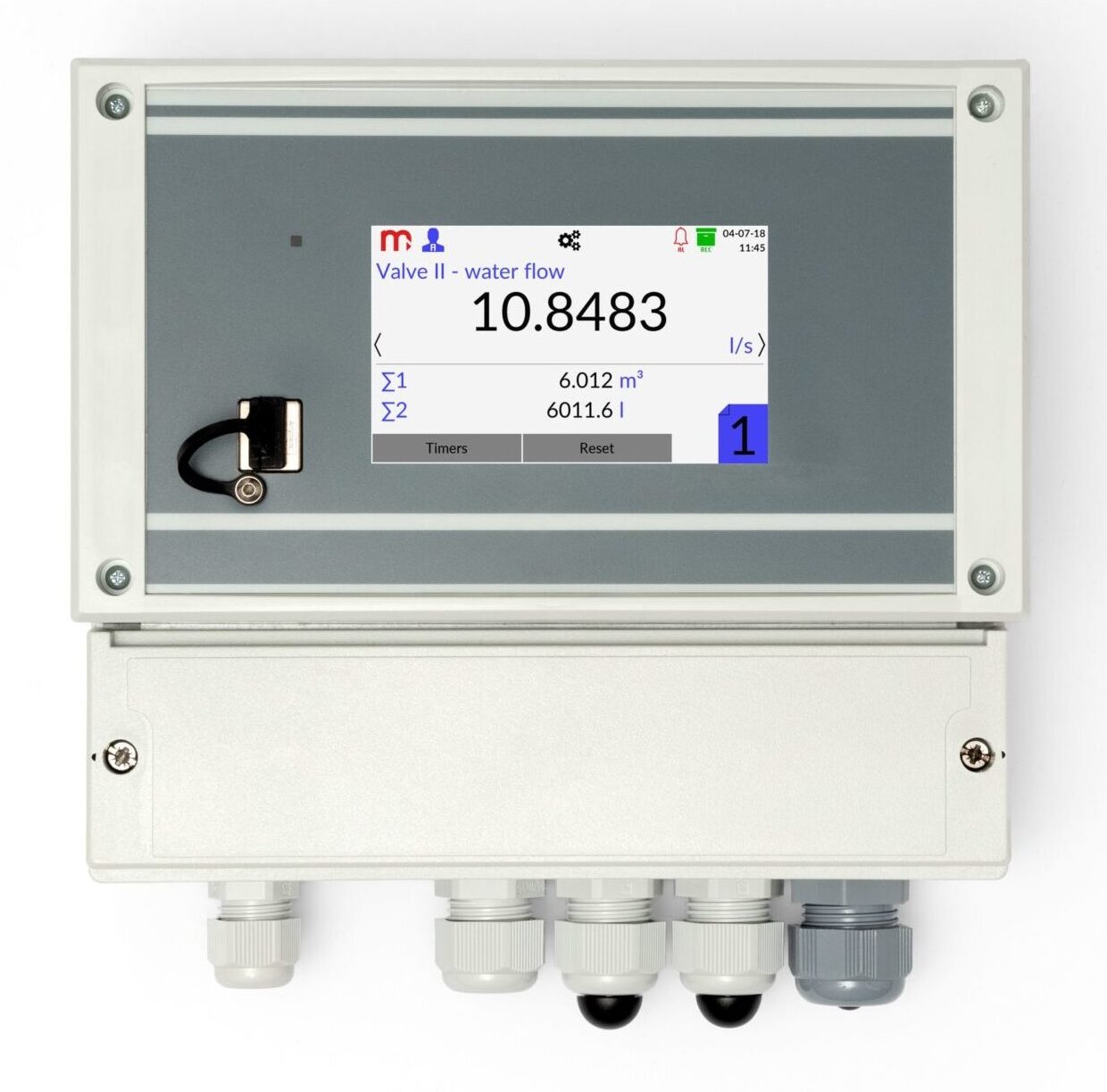
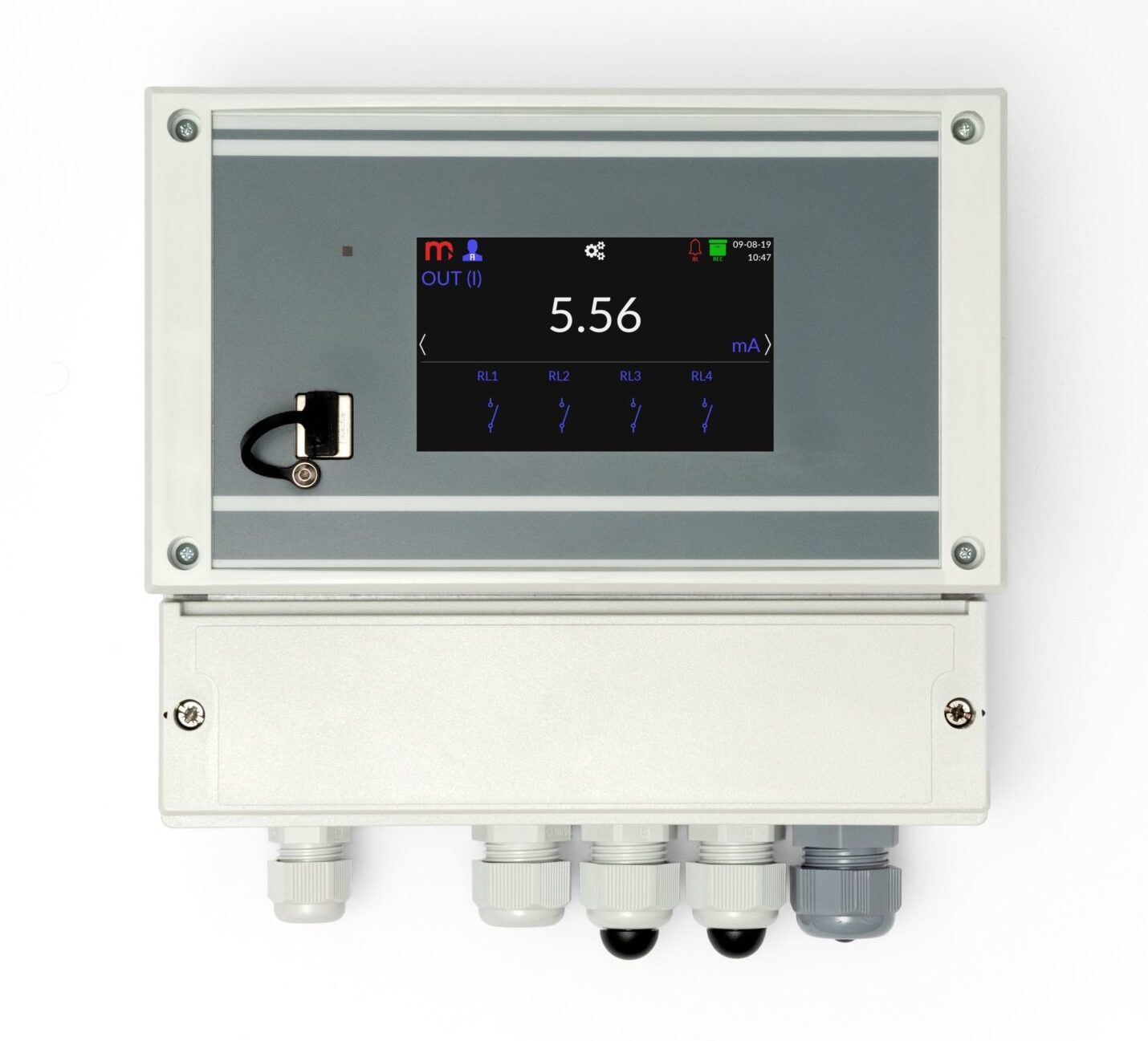
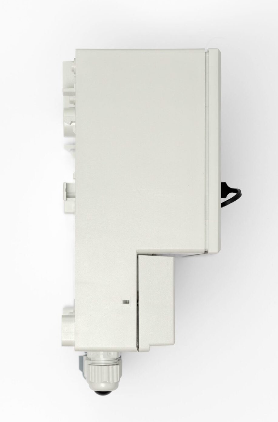

Flow totalizer with data recording
• 2 analog inputs
• 2 PULS inputs
• 2 math channels
• 4-20mA analog output
• 4 solid state relays
• USB port on front panel
• Ethernet port (Modbus TCP protocol, server www)
• RS-485 port (Modbus RTU protocol)
• E-mail notifications, information about alarms, cycilc reports with totalizers value
• 4” Touch screen LCD
• Internal memory 2 GB
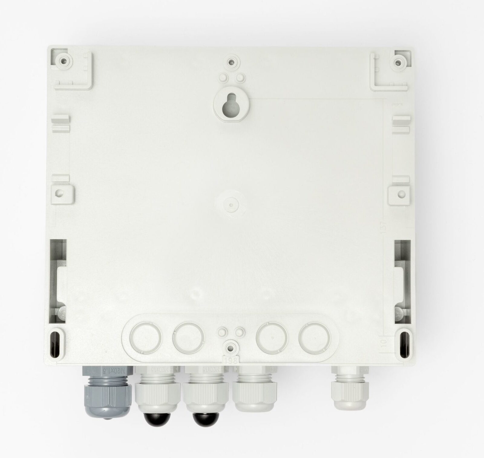
• Case for wall mounting.
2 ANALOG INPUTS
Independent setup for input sensors
• Transducers with 4-20mA (with optional power supply from device) or 0-20mA current loop output
• RTD sensors (Pt100, Pt200, Pt500, Pt1000)
• Transducers with 0…2500 Ω resistance output
• Transducers with –1 V…+1 V or –10 V…+10 V voltage output
2 PULS INPUTS
• Frequency measurement in range 0,01 Hz … 10 kHz
• Counting pulses
• Tracking and recording of binary signal (shorting or disconnecting)
ANALOG OUTPUT
• Retransmission of one of the channels as a 4-20mA current loop output signal
TOTALIZERS
• For each input there are available two totalizers L1 and L2
• Totalizers can be reset manually or they can work automatically: daily ,weekly or monthly
• Totalizers T1 and T2 counting the operation time of totalizers
• Frequency of archiving, for counters, from 1 min to 24h
4 ALARM AND CONTROL SYSTEM
• 4 solid state relays 0,1 A / 60 V
• 2 alarm and control thresholds for each channel
RECORDING MEASUREMENT RESULT
• Recording data to internal 2GB memory, local access to recorded data through USB port on the front panel
• Data recording rate between 2 s and 24 h; two recording frequencies toggled upon exceeding the set alarm thresholds
INTENDED USE
• Measurement of flow and other quantities, e.g. temperature, humidity, pressure
• Operation in dispersed measurement systems with local readings of measurement results
• Grocery, steel, metallurgical, glass-making industry, warehouse and production line control
This product is CE marked.
Declarations of Conformity are available on request.
| Front panel (FP4, FP4W) | |
| Type of display
|
LCD TFT 4” 800 px X 480 px
LED backlight |
| Display size | 86.4 mm X 52.5 mm |
| Keyboard | resistive touch panel |
| Additional indication | LED RGB |
| USB Port – front panel (FP4, FP4W) | |
| Version | USB 2.0 (with limited functionality, for connection of FLASH storage) |
| Connector type | USB standard ‘A’ type socket |
| Files system | FAT16, FAT32(1) |
| (1)Compatibility of all USB memory devices is not guaranteed. | |
| Ethernet Port (FP4, FP4W) | |
| Interface | 10/100Base-T Ethernet |
| Connector type | RJ-45 |
| Transmission protocol | Server WWW, Modbus TCP
ICMP (ping) |
| Number of connections opened simultaneously | Max 4 |
| RS-485 Serial Port (FP4, FP4W) | |
| Signals output on terminal block | A(+), B(-) |
| Galvanic isolation | None |
| Maximum load | 32 receivers/transmitters |
| Transmission protocol | Modbus RTU Slave |
| Transmission rate | 1.2, 2.4, 4.8, 9.6, 19.2, 38.4, 57.6, 115.2 kbps |
| Parity control | Even, Odd, None |
| Frame | 1 start bit, 8 data bits, 1 stop bit |
| Maximum length of line | 1200 m |
| Internal terminating resistor | Vcc-A(+)-B(-)-G: 390 Ω – 220 Ω – 390 Ω
(activated by DIP-switches) |
| Maximum differntial voltage A(+), B(-) | -7 .. +12 V |
| Minimum output signal of transmitter | 1.5 V (at RL= 54 W) |
| Minimum sensitivity of receiver | 200 mV / RIN= 12 kW |
| Minimum impedance of data transmission line | 54 W |
| Short-circuit/thermal protection | Yes/Yes |
| Internal data memory (FP4, FP4W) | |
| Memory type | Flash |
| Capacity | 2 GB |
| Estimated recording time for recording speed every 2 s for 6 measuring channels | ca. 2 years
|
| Supply (FP4) | |
| Supply voltage | 24 VDC (20 .. 30 VDC) |
| Maximum power consumption | 6 W (typically 4 W) |
| Security | The internal delay fuse 3.15 A, the exchange only by the service company |
| Supply (FP4W) | |
| Supply voltage | 100 .. 240 VAC 50/60 Hz or 24 VDC (20 .. 30 VDC) |
| Maximum power consumption | · for 100 .. 240 VAC 50/60 Hz power supply:
8 W (typically 6 W) · for 24 VDC (20 .. 30 VDC) power supply: 6 W (typically 4 W) |
| Security | The internal delay fuse 3.15 A, the exchange only by the service company |
| Output 24 V OUT (FP4W) | |
| Output voltage (on 24 V OUT) | unregulated 18 .. 26 VDC |
| Maximum load current (on 24 V OUT) | 100 mA |
| Electrical connections (FP4) | |
| Type | screw terminal connectors |
| Wire cross section | solid and flexible 0.14 .. 1.5 mm2
flexible with bootlace ferrule 0.25 .. 1.5 mm2 AWG 30/14 |
| Electrical connections (FP4W) | |
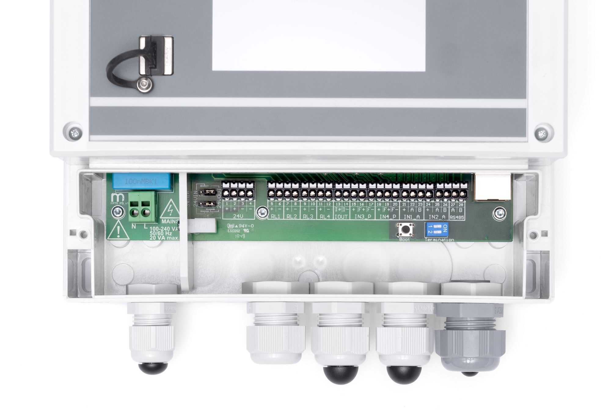
| Type | spring type terminal block |
| Wire cross section | · supply 230 VAC: 0.2 .. 2.5 mm2
· others: 0.2 .. 1.5 mm2 |
| Cable glands | · supply: one M16 cable gland, cable diameter: 5 .. 10 mm· I/O signals: three M20 cable glands, cable diameter: 8 .. 13 mm· Ethernet: one M20 cable gland, cable diameter: 6 mm (the possibility of installing a cable with an RJ-45 connector) |
| Mechanical Dimensions – enclosure (FP4) | |
| Enclosure type | panel mount, nonflammable plastic material „Noryl” |
| Dimensions with connectors (w X h X d) | 144 mm X 72 mm X 127 mm |
| Dimensions of panel cut-out (w X h) | 138+1 mm X 68+0.7 mm |
| Maximum panel thickness | 5 mm |
| Weight | 0.5 kg |
| Protection class | IP30 on front panel side
IP30 on rear panel side |
| Mechanical Dimensions – enclosure (FP4W) | |
| Enclosure type | Wall mount, polycarbonate material |
| Dimensions (w X h X d) | · without cable glands:
213 mm x 185 mm x 102 mm · with cable glands: 213 mm x 215 mm x 102 mm |
| Weight | c.a. 0.8 kg |
| Protection class | IP54 |
| Environmental conditions (FP4, FP4W) | |
| Ambient temperature | · FP4: 0 .. +50 °C
· FP4W: -20 .. +50 °C |
| Relative humidity | 5 .. 95% (without steam condensation) |
| Maximum altitude | <2000 m above sea level |
| Storage temperature | -30 .. +70 °C |
| Degree of pollution | PD2 |
| EMC | EMC Directive 2014/30/EU
EN 61326-1:2013 Table 2 (immunity) EN 61326-1:2013 Class A (emission) |
| RoHS | RoHS Directive 2011/65/EU |
| Installation location | · FP4: Indoor only
· FP4W: Indoor or outdoor(2) |
| (2)If additional protection against atmospheric precipitation is provided (roofing), the device can be installed outdoor. | |
| ANALOGUE INPUTS (FP4, FP4W) | |
| Number of inputs | 2 (input type (0/4-20mA/RTD/U) configurable by jumpers inside the device) |
| Update rate | 0.5 s/display every 1 s |
| Low-pass digital filter (damping filter)(3) | A time constant programmed in the range 2 .. 60 s |
| Galvanic isolation between inputs | None |
| Galvanic isolation from the other circuits | Functional, 250 VAC |
| Maximum input voltage | ±30 VDC between terminals A(I+), B(I-) |
| Configuration: 0/4-20mA input(4) | |
| Measurement range | 0 .. 22 mA |
| Input resistance | <100 Ω |
| Initial accuracy (Ta=+25 °C) | ±0.1% of range (typically ±0.05% of range) |
| Conversion characteristic | Linear or User |
| Transducers powered from recorder | 24 VDC (+10/-20%), 24 mA (current-limited polymer fuse) |
| (4)The device is delivered in the 0/4-20mA configuration. | |
| Configuration: R/RTD input | |
| Sensor type | · Resistive (refer the table below)
· Linear resistance |
| Sensor connection type | 2-wire |
| Sensor current | 420 μA |
| Wire resistance compensation in the 2-wire connection | User programmed in the range of -99 .. +99 Ω |
| Resistance of wires (to the sensor) | max 50 Ω |
| Transducer resistance range | 0 .. 2700 Ω |
| Initial accuracy (Ta=+25 °C) | ±0.5 Ω (typically ±0.3 Ω) |
| Conversion characteristic for R | Linear, User or sensors |
| RTD sensor type, range and accuracy | Refer the table below |
| Configuration: U (±10 V) input | |
| Voltage range | -10 .. +10 V |
| Input resistance | >10 kΩ |
| Conversion characteristic (for U) | Linear or User |
| Initial accuracy (Ta=+25 °C) | ±0.5% of range |
| PULS TYPE INPUTS (FP4, FP4W) | |
| Number of inputs | 2 |
| Measurement range | · 0.01 Hz .. 10 kHz, additional filter disabled
· 0.01 Hz .. 1 kHz, additional filter enabled |
| Minimum pulse width | · 50 μs, additional filter disabled
· 0.5 ms, additional filter enabled |
| Maximum input voltage | ±30 VDC (between terminals F+ and F-) |
| Frequency measurement | |
| Conversion characteristic | Linear or User |
| Initial accuracy (Ta=+25 °C) | 0.05% * f ±0.1 Hz |
| Pulse counting | |
| Conversion characteristic | Linear |
| Measuring range | 0 .. 10 kHz |
| Initial accuracy (Ta=+25 °C) | 0.05% * f ±0.1 Hz
(without losing pulses in the counters) |
| Configuration: OC/contact(5) | |
| Open contact voltage | ca. 4.3 V |
| Short circuit current | ca. 4.3 mA |
| Switch on/off threshold | ca. 2.4 V / 2.6 V |
| Maximum short circuit resistance | 100 Ω |
| (5)The device is delivered in the OC/contact configuration, with the additional filtering capacitor disconnected. | |
| Configuration: current input NAMUR | |
| Input resistance | 1.5 kΩ |
| Switch on/off threshold | ca. 1.6 mA / 1.8 mA |
| Configuration: current input EH | |
| Input resistance | 200 Ω |
| Switch on/off threshold | ca. 11 mA / 13 mA |
| Configuration: voltage input | |
| Input resistance | >10 kΩ |
| Switch on/off threshold | ca. 2.4 V / 2.6 V |
| Maximum input voltage | ±30 VDC |
| RELAY OUTPUTS (FP4, FP4W) | |
| Number of outputs | 4 |
| Outputs type | Solid state relays |
| Maximum voltage | 60 V AC/DC |
| Maximum load current | 0.1 A |
| ANALOGUE OUTPUT 4-20mA (FP4, FP4W) | |
| Output signal | 4-20 mA (3.6 .. 22 mA) |
| Current loop supply | no (external supply required) |
| Maximum voltage between I+ and I- | 28 VDC |
| Minimum supply current loop voltage | 9 VDC (RL=0 Ω) |
| Loop resistance (RL) | 0 .. 500 Ω |
| Accuracy | 0.2% |
| Galvanic isolation to supply voltage | Functional, 250 VAC |









Flow totalizer with data recording
• 2 analog inputs
• 2 PULS inputs
• 2 math channels
• 4-20mA analog output
• 4 solid state relays
• USB port on front panel
• Ethernet port (Modbus TCP protocol, server www)
• RS-485 port (Modbus RTU protocol)
• E-mail notifications, information about alarms, cycilc reports with totalizers value
• 4” Touch screen LCD
• Internal memory 2 GB
• Case for wall mounting.
2 ANALOG INPUTS
Independent setup for input sensors
• Transducers with 4-20mA (with optional power supply from device) or 0-20mA current loop output
• RTD sensors (Pt100, Pt200, Pt500, Pt1000)
• Transducers with 0…2500 Ω resistance output
• Transducers with –1 V…+1 V or –10 V…+10 V voltage output
2 PULS INPUTS
• Frequency measurement in range 0,01 Hz … 10 kHz
• Counting pulses
• Tracking and recording of binary signal (shorting or disconnecting)
ANALOG OUTPUT
• Retransmission of one of the channels as a 4-20mA current loop output signal
TOTALIZERS
• For each input there are available two totalizers L1 and L2
• Totalizers can be reset manually or they can work automatically: daily ,weekly or monthly
• Totalizers T1 and T2 counting the operation time of totalizers
• Frequency of archiving, for counters, from 1 min to 24h
4 ALARM AND CONTROL SYSTEM
• 4 solid state relays 0,1 A / 60 V
• 2 alarm and control thresholds for each channel
RECORDING MEASUREMENT RESULT
• Recording data to internal 2GB memory, local access to recorded data through USB port on the front panel
• Data recording rate between 2 s and 24 h; two recording frequencies toggled upon exceeding the set alarm thresholds
INTENDED USE
• Measurement of flow and other quantities, e.g. temperature, humidity, pressure
• Operation in dispersed measurement systems with local readings of measurement results
• Grocery, steel, metallurgical, glass-making industry, warehouse and production line control
This product is CE marked.
Declarations of Conformity are available on request.

| Front panel (FP4, FP4W) | |
| Type of display
|
LCD TFT 4” 800 px X 480 px
LED backlight |
| Display size | 86.4 mm X 52.5 mm |
| Keyboard | resistive touch panel |
| Additional indication | LED RGB |
| USB Port – front panel (FP4, FP4W) | |
| Version | USB 2.0 (with limited functionality, for connection of FLASH storage) |
| Connector type | USB standard ‘A’ type socket |
| Files system | FAT16, FAT32(1) |
| (1)Compatibility of all USB memory devices is not guaranteed. | |
| Ethernet Port (FP4, FP4W) | |
| Interface | 10/100Base-T Ethernet |
| Connector type | RJ-45 |
| Transmission protocol | Server WWW, Modbus TCP
ICMP (ping) |
| Number of connections opened simultaneously | Max 4 |
| RS-485 Serial Port (FP4, FP4W) | |
| Signals output on terminal block | A(+), B(-) |
| Galvanic isolation | None |
| Maximum load | 32 receivers/transmitters |
| Transmission protocol | Modbus RTU Slave |
| Transmission rate | 1.2, 2.4, 4.8, 9.6, 19.2, 38.4, 57.6, 115.2 kbps |
| Parity control | Even, Odd, None |
| Frame | 1 start bit, 8 data bits, 1 stop bit |
| Maximum length of line | 1200 m |
| Internal terminating resistor | Vcc-A(+)-B(-)-G: 390 Ω – 220 Ω – 390 Ω
(activated by DIP-switches) |
| Maximum differntial voltage A(+), B(-) | -7 .. +12 V |
| Minimum output signal of transmitter | 1.5 V (at RL= 54 W) |
| Minimum sensitivity of receiver | 200 mV / RIN= 12 kW |
| Minimum impedance of data transmission line | 54 W |
| Short-circuit/thermal protection | Yes/Yes |
| Internal data memory (FP4, FP4W) | |
| Memory type | Flash |
| Capacity | 2 GB |
| Estimated recording time for recording speed every 2 s for 6 measuring channels | ca. 2 years
|
| Supply (FP4) | |
| Supply voltage | 24 VDC (20 .. 30 VDC) |
| Maximum power consumption | 6 W (typically 4 W) |
| Security | The internal delay fuse 3.15 A, the exchange only by the service company |
| Supply (FP4W) | |
| Supply voltage | 100 .. 240 VAC 50/60 Hz or 24 VDC (20 .. 30 VDC) |
| Maximum power consumption | · for 100 .. 240 VAC 50/60 Hz power supply:
8 W (typically 6 W) · for 24 VDC (20 .. 30 VDC) power supply: 6 W (typically 4 W) |
| Security | The internal delay fuse 3.15 A, the exchange only by the service company |
| Output 24 V OUT (FP4W) | |
| Output voltage (on 24 V OUT) | unregulated 18 .. 26 VDC |
| Maximum load current (on 24 V OUT) | 100 mA |
| Electrical connections (FP4) | |
| Type | screw terminal connectors |
| Wire cross section | solid and flexible 0.14 .. 1.5 mm2
flexible with bootlace ferrule 0.25 .. 1.5 mm2 AWG 30/14 |
| Electrical connections (FP4W) | |
| Type | spring type terminal block |
| Wire cross section | · supply 230 VAC: 0.2 .. 2.5 mm2
· others: 0.2 .. 1.5 mm2 |
| Cable glands | · supply: one M16 cable gland, cable diameter: 5 .. 10 mm· I/O signals: three M20 cable glands, cable diameter: 8 .. 13 mm· Ethernet: one M20 cable gland, cable diameter: 6 mm (the possibility of installing a cable with an RJ-45 connector) |
| Mechanical Dimensions – enclosure (FP4) | |
| Enclosure type | panel mount, nonflammable plastic material „Noryl” |
| Dimensions with connectors (w X h X d) | 144 mm X 72 mm X 127 mm |
| Dimensions of panel cut-out (w X h) | 138+1 mm X 68+0.7 mm |
| Maximum panel thickness | 5 mm |
| Weight | 0.5 kg |
| Protection class | IP30 on front panel side
IP30 on rear panel side |
| Mechanical Dimensions – enclosure (FP4W) | |
| Enclosure type | Wall mount, polycarbonate material |
| Dimensions (w X h X d) | · without cable glands:
213 mm x 185 mm x 102 mm · with cable glands: 213 mm x 215 mm x 102 mm |
| Weight | c.a. 0.8 kg |
| Protection class | IP54 |
| Environmental conditions (FP4, FP4W) | |
| Ambient temperature | · FP4: 0 .. +50 °C
· FP4W: -20 .. +50 °C |
| Relative humidity | 5 .. 95% (without steam condensation) |
| Maximum altitude | <2000 m above sea level |
| Storage temperature | -30 .. +70 °C |
| Degree of pollution | PD2 |
| EMC | EMC Directive 2014/30/EU
EN 61326-1:2013 Table 2 (immunity) EN 61326-1:2013 Class A (emission) |
| RoHS | RoHS Directive 2011/65/EU |
| Installation location | · FP4: Indoor only
· FP4W: Indoor or outdoor(2) |
| (2)If additional protection against atmospheric precipitation is provided (roofing), the device can be installed outdoor. | |
| ANALOGUE INPUTS (FP4, FP4W) | |
| Number of inputs | 2 (input type (0/4-20mA/RTD/U) configurable by jumpers inside the device) |
| Update rate | 0.5 s/display every 1 s |
| Low-pass digital filter (damping filter)(3) | A time constant programmed in the range 2 .. 60 s |
| Galvanic isolation between inputs | None |
| Galvanic isolation from the other circuits | Functional, 250 VAC |
| Maximum input voltage | ±30 VDC between terminals A(I+), B(I-) |
| Configuration: 0/4-20mA input(4) | |
| Measurement range | 0 .. 22 mA |
| Input resistance | <100 Ω |
| Initial accuracy (Ta=+25 °C) | ±0.1% of range (typically ±0.05% of range) |
| Conversion characteristic | Linear or User |
| Transducers powered from recorder | 24 VDC (+10/-20%), 24 mA (current-limited polymer fuse) |
| (4)The device is delivered in the 0/4-20mA configuration. | |
| Configuration: R/RTD input | |
| Sensor type | · Resistive (refer the table below)
· Linear resistance |
| Sensor connection type | 2-wire |
| Sensor current | 420 μA |
| Wire resistance compensation in the 2-wire connection | User programmed in the range of -99 .. +99 Ω |
| Resistance of wires (to the sensor) | max 50 Ω |
| Transducer resistance range | 0 .. 2700 Ω |
| Initial accuracy (Ta=+25 °C) | ±0.5 Ω (typically ±0.3 Ω) |
| Conversion characteristic for R | Linear, User or sensors |
| RTD sensor type, range and accuracy | Refer the table below |
| Configuration: U (±10 V) input | |
| Voltage range | -10 .. +10 V |
| Input resistance | >10 kΩ |
| Conversion characteristic (for U) | Linear or User |
| Initial accuracy (Ta=+25 °C) | ±0.5% of range |
| PULS TYPE INPUTS (FP4, FP4W) | |
| Number of inputs | 2 |
| Measurement range | · 0.01 Hz .. 10 kHz, additional filter disabled
· 0.01 Hz .. 1 kHz, additional filter enabled |
| Minimum pulse width | · 50 μs, additional filter disabled
· 0.5 ms, additional filter enabled |
| Maximum input voltage | ±30 VDC (between terminals F+ and F-) |
| Frequency measurement | |
| Conversion characteristic | Linear or User |
| Initial accuracy (Ta=+25 °C) | 0.05% * f ±0.1 Hz |
| Pulse counting | |
| Conversion characteristic | Linear |
| Measuring range | 0 .. 10 kHz |
| Initial accuracy (Ta=+25 °C) | 0.05% * f ±0.1 Hz
(without losing pulses in the counters) |
| Configuration: OC/contact(5) | |
| Open contact voltage | ca. 4.3 V |
| Short circuit current | ca. 4.3 mA |
| Switch on/off threshold | ca. 2.4 V / 2.6 V |
| Maximum short circuit resistance | 100 Ω |
| (5)The device is delivered in the OC/contact configuration, with the additional filtering capacitor disconnected. | |
| Configuration: current input NAMUR | |
| Input resistance | 1.5 kΩ |
| Switch on/off threshold | ca. 1.6 mA / 1.8 mA |
| Configuration: current input EH | |
| Input resistance | 200 Ω |
| Switch on/off threshold | ca. 11 mA / 13 mA |
| Configuration: voltage input | |
| Input resistance | >10 kΩ |
| Switch on/off threshold | ca. 2.4 V / 2.6 V |
| Maximum input voltage | ±30 VDC |
| RELAY OUTPUTS (FP4, FP4W) | |
| Number of outputs | 4 |
| Outputs type | Solid state relays |
| Maximum voltage | 60 V AC/DC |
| Maximum load current | 0.1 A |
| ANALOGUE OUTPUT 4-20mA (FP4, FP4W) | |
| Output signal | 4-20 mA (3.6 .. 22 mA) |
| Current loop supply | no (external supply required) |
| Maximum voltage between I+ and I- | 28 VDC |
| Minimum supply current loop voltage | 9 VDC (RL=0 Ω) |
| Loop resistance (RL) | 0 .. 500 Ω |
| Accuracy | 0.2% |
| Galvanic isolation to supply voltage | Functional, 250 VAC |


