Data loggers
MPI-DN
Data logger with 2GB internal flash memory in wall-mounted case. The recorder is intended to measure process values in industrial applications. It is designed to work with devices and sensors that communicates by digital bus: RS-485 standard with Modbus RTU protocol and HART standard (also in multidrop configuration).
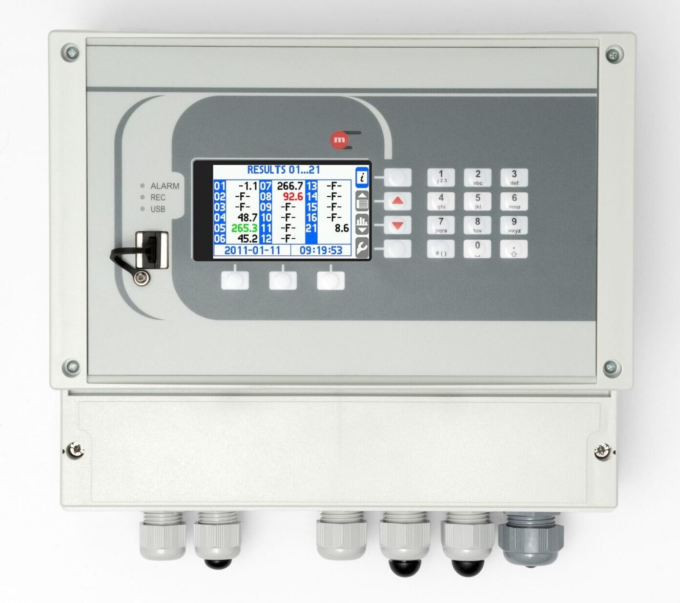
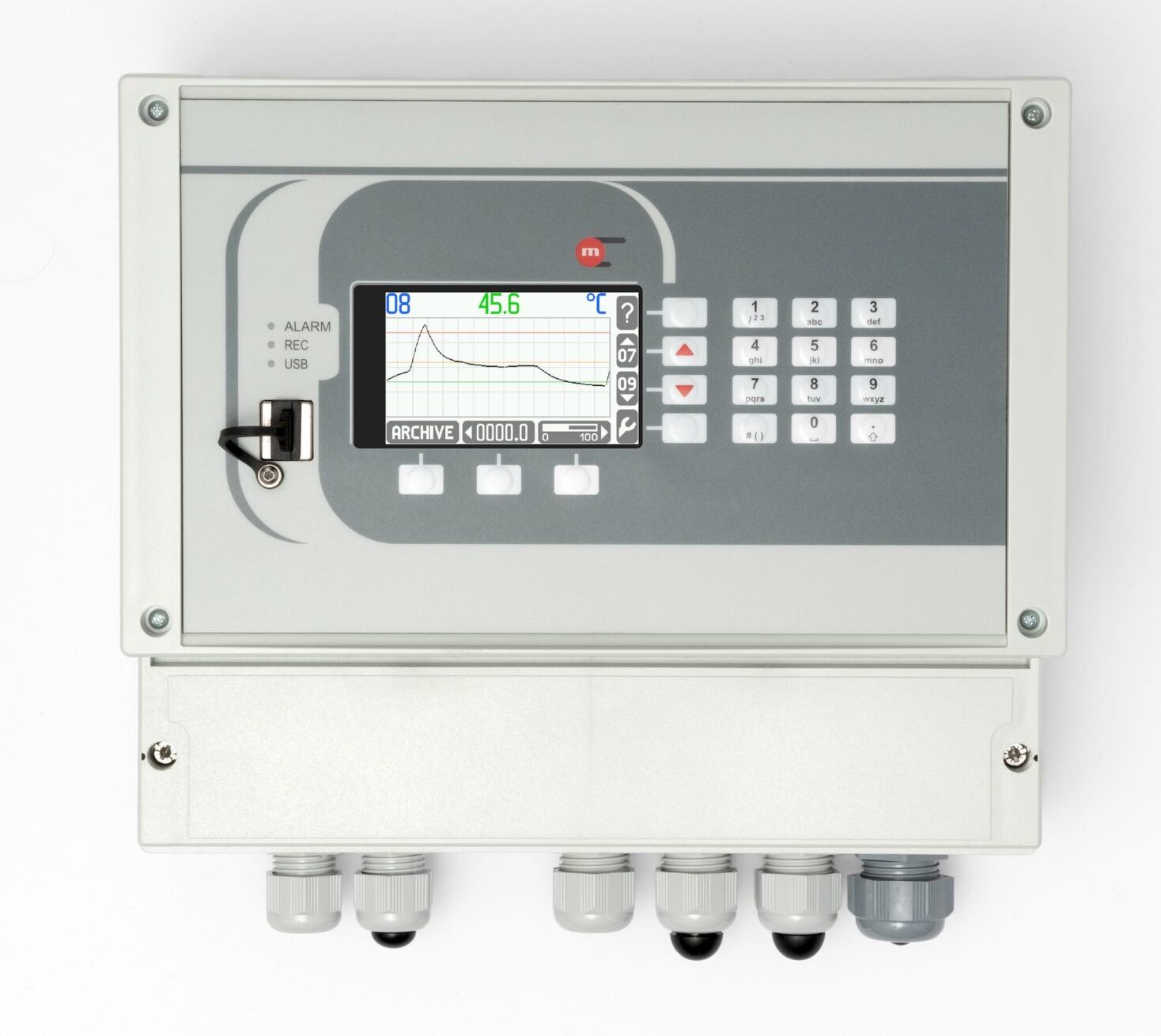
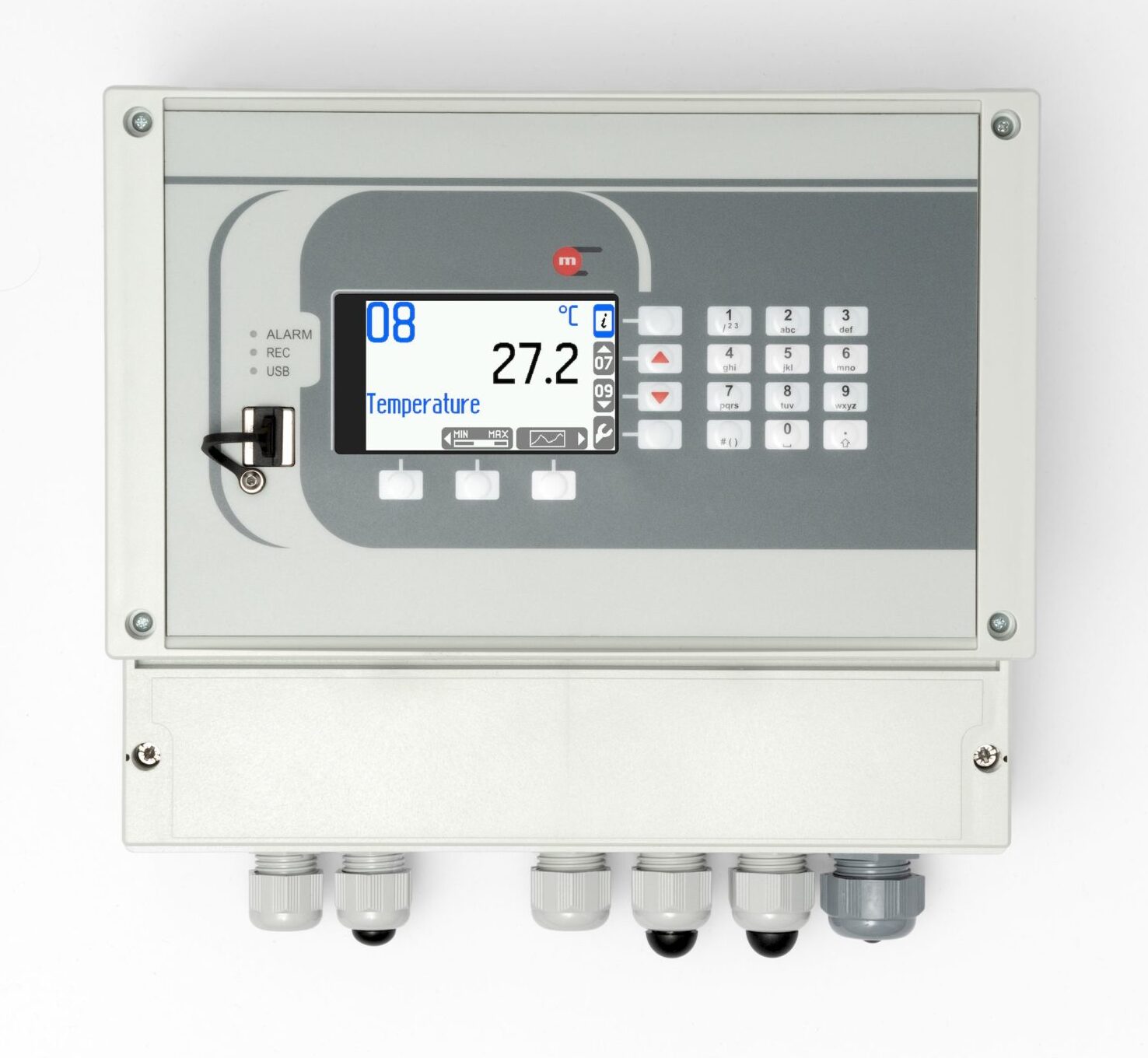


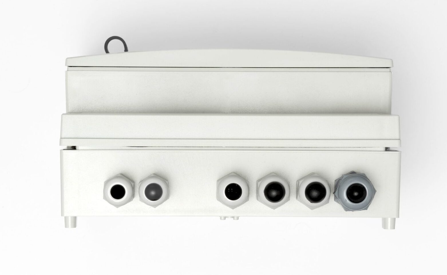
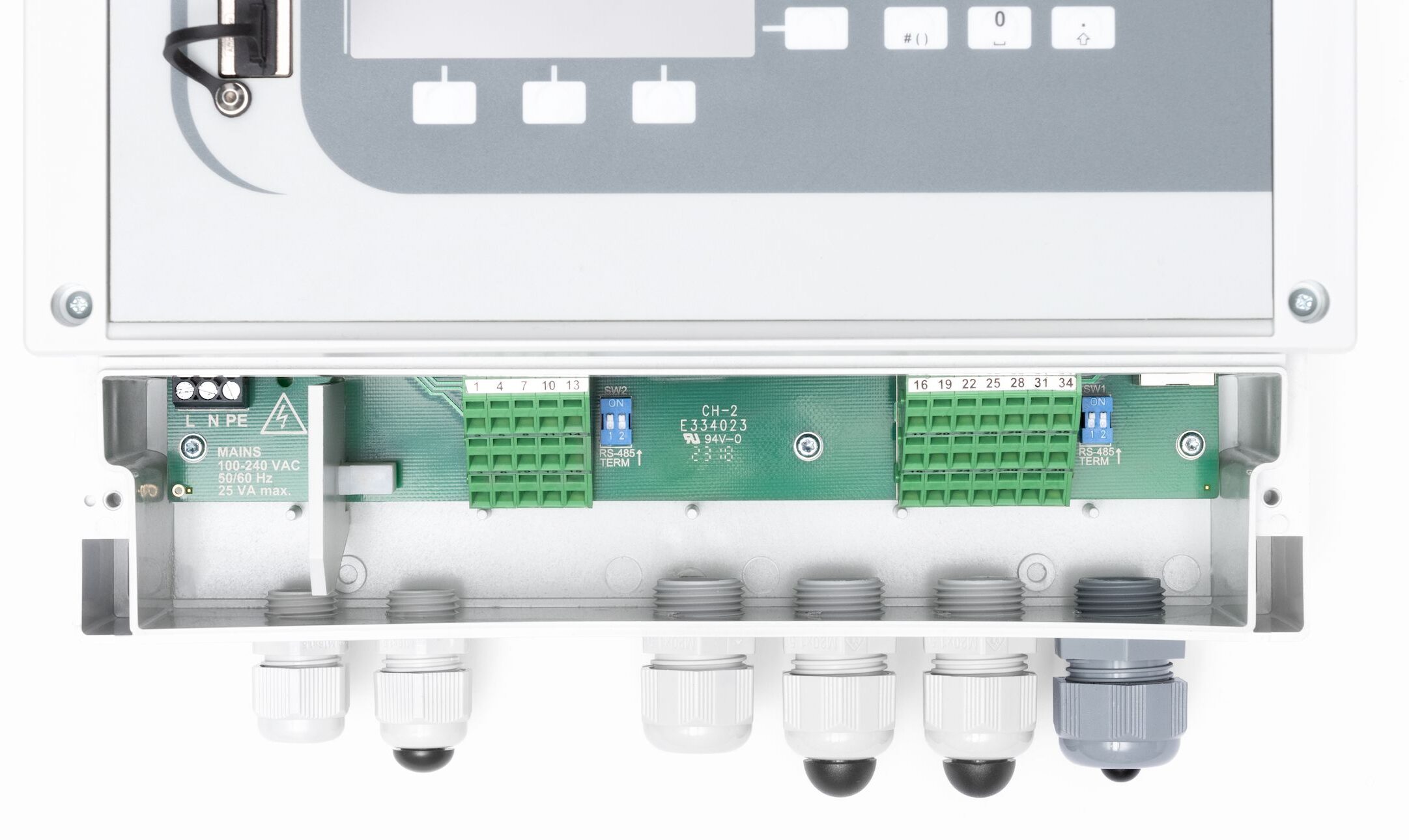
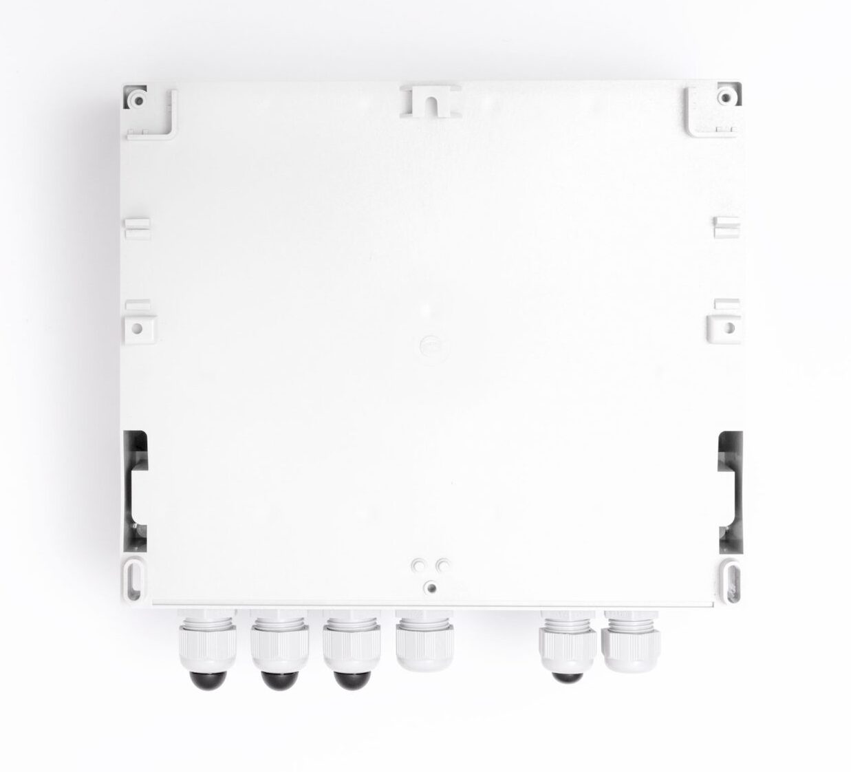
Multi-channel data logger in wall-mounted case
• 20 measuring channels
• Interaction with RS-485 / Modbus RTU transducers and devices and HART devices (also in multidrop mode)
• 2 binary inputs
• 16 calculation channels
• 4 relay outputs – alarm and control functions
• Internal 2GB data memory, advanced data recording
• Color graphic LCD TFT display
• USB port on front panel with IP54 protection
• Ethernet port (Modbus TCP protocol, server www)
• RS-485 port (Modbus RTU protocol)
• Dedicated software for visualization of measurement results
• Wall-mounted case
• 19-buttons extended keyboard version (makes it easier to enter and edit numbers, text, formulas and passwords)
• Powered with 230 V
Measurment channels
• 18 channels intended for reading transducers or other devices operating in the Modbus RTU standard and HART protocol transducers
• 2 channels intended for interaction with PULS-type inputs (measurement of frequencies within the range of 0.001Hz … 10kHz, pulse counting, tracking and recording the shorting / disconnecting binary signal)
HART
• Readout of digital quantities from transducers / devices connected in parallel to a current loop
• Operation as Primary Master or Secondary Master
• Readout of variables: PV – primary variable, SV – secondary variable, TV – third variable, FV – fourth variable
MODBUS RTU
• Devices / transducers connected in parallel to one pair of wires (of an RS-485(1) port)
• Transmission rate between 1200bps and 115,200bps
• Readout functions: 03 (Read Holding Register) and 04 (Read Input Register)
• Supported formats of variables: Uns. Integer, Integer, Uns. Long, Uns. Long(sw), Long, Long(sw), Float, Float(sw)
16 Calculated values
• Available functions: addition, subtraction, multiplication, division and extraction of roots
Recording measurement results
• Recording to internal 2GB memory
• Checksum secured files – protection against result errors
• Recording frequency between 3 s and 24 h; define two recording frequencies toggled upon exceeding the set alarm thresholds
4 relay outputs, alarm and control thresholds
• 4 semiconducting output relays rated at 0.1A / 60V
• Up to 4 alarm thresholds for each input and each calculated value
Other functions
• Totalizers – two totalizers per flow value (measured or calculated)
• Tracking minimum, maximum and average values
• Advanced user and password system
• Event Log
• Authorized Operations Log
• Available also in panel case – MPI-D
Application
The MPI-D, MPI-DN recorders are used in the energy, chemical, pharmaceutical, food, metallurgical industries, manufacturing, laboratories, and wherever it is necessary to register digital measurement. Example of application: monitoring of compressed air and gas flow parameters.
This product is CE marked.
Declarations of Conformity are available on request.
| FRONT PANEL | ||
| Display type | LCD TFT colour 272×480 px | |
| Display size | 43.8 mm x 77.4 mm | |
| Keyboard | · MPI-D: 7 membrane buttons
· MPI-DN: 19 membrane buttons |
|
| LED indication | 3 LEDs 3-colour, red-orange-green | |
| INPUTS ORGANIZATION | ||
| MPI-D, MPI-DN |
Port HART: Port RS-485 (1): 2 x PULS: IN19, IN20 |
|
| RS-485 (1) serial port – Master | ||
| Transmission protocol | Modbus RTU | |
| Data format | Uns. Integer, Integer, Uns. Long, Uns. Long (sw), Long, Long (sw), Float, Float (sw) | |
| Frequency of reading | 3 s, 4 s, 5 s, 6 s, 10 s, 12 s, 15 s, 30 s, 1 min | |
| Baud rate | 1.2, 2.4, 4.8, 9.6, 19.2, 38.4, 57.6, 115.2 kbps | |
| Address space of transducers | 1 .. 247 | |
| Maximum load | 32 receivers/transmitters | |
| Maximum line length | 1200 m | |
| Maximum differential voltage A(+) – B(-) | -7 .. +12 V | |
| Maximum total voltage A(+) – ‘ground’ or B(-) – ‘ground’ |
-7 .. +12 V | |
| Minimal output signal from transmitter | 1.5 V (for R0 = 54 Ω) | |
| Minimum receiver sensitivity | 200 mV / RIN = 12 kΩ | |
| Minimum impedance of data transmission line | 54 Ω | |
| Internal terminating resistor | Yes, activated by short-circuit pins on terminal block | |
| Short-circuit/thermal protection | Yes/Yes | |
| Galvanic isolation from supply voltage | 400 VAC (functional isolation) | |
| HART port | ||
| Transmission protocol | Master type 0 or 1, rev. 4, rev. 5, rev. 6; FSK | |
| Implemented features | Reading variables PV, SV, TV, FV
Retrieve long address (rev. 5, rev. 6) Change of short address |
|
| Multidrop mode | Yes, up to 12 devices | |
| Loop power | 24 VDC (max 50 mA) | |
| Analog line 4-20mA reading | No | |
| Galvanic isolation from supply voltage | 400 VAC (functional isolation) | |
| PULS type inputs (binary/pulse/frequency) | ||
| Number of inputs | 2 | |
| Maximum input voltage | ±28 VDC | |
| Galvanic isolation from supply voltage | 400 VAC (functional isolation) | |
| Functions | State detection
Pulse counting Frequency measurement |
|
| Measuring range | 0.001 Hz .. 10 kHz
(0.001 Hz .. 1 kHz with filtrating capacitor) |
|
| Minimum impulse width | 20 ms
0.5 ms with filtrating capacitor |
|
| Accuracy (at Ta = +20 °C) | 0.02% | |
| Configuration: OC/contact(1) | ||
| Open circuit voltage | 12 V | |
| Short circuit current | 12 mA | |
| On/off threshold | 2.7 V / 2.4 V | |
| (1)The default setting. | ||
| Configuration: voltage input | ||
| Input resistance | 1 kW | |
| On/off threshold | 2.7 V / 2.4 V | |
| Open circuit voltage | 12 V | |
| Configuration: Namur | ||
| High impedance state | 0.4 .. 1 mA | |
| Low impedance state | 2.2 .. 6.5 mA | |
| Binary outputs (Solid State Relays) | ||
| Number of outputs | 4 | |
| Type of outputs | Solid State Relays | |
| Maximum load current | 100 mA DC/AC | |
| Maximum voltage | 60 V DC/AC | |
| Galvanic isolation between outputs | 400 VAC (functional isolation) | |
| Galvanic isolation from supply voltage | 400 VAC (functional isolation) | |
| 4-20mA analogue output (optional) | ||
| Number of outputs | 1 | |
| Output signal | 4-20mA (3.6–22 mA) | |
| Maximum voltage between I+ and I- | 28 VDC | |
| Loop resistance (at Ucc = 24 V) | 0 .. 500 Ω | |
| Converter resolution D/A | 16 bit | |
| Accuracy | 0.5% | |
| Current loop supply | External or internal power supply 24 VDC / 22 mA | |
| Galvanic isolation from supply voltage | 400 VAC (functional isolation) | |
| RS-485 (2) serial port – Slave | ||
| Maximum load | 32 receivers/transmitters | |
| Maximum line length | 1200 m | |
| Maximum differential voltage A(+) – B(-) | -7 .. +12 V | |
| Maximum total voltage A(+) – ‘ground’ or B(-) – ‘ground’ |
-7 .. +12 V | |
| Minimal output signal from transmitter | 1.5 V (for R0 = 54 W) | |
| Minimum receiver sensitivity | 200 mV / RIN = 12 kW | |
| Minimum impedance of data transmission line | 54 W | |
| Internal terminating resistor | Yes, activated by short-circuit pins on terminal block | |
| Short-circuit/thermal protection | Yes/Yes | |
| Transmission protocol | ASCII
Modbus RTU |
|
| Baud rate | 2.4, 4.8, 9.6 ,19.2, 38.4, 57.6, 115.2 kbps | |
| Parity control | Even, Odd, None | |
| Frame | 1 start bit, 8 data bits, 1 stop bit | |
| Galvanic isolation | No | |
| Ethernet port | ||
| Transmission protocol | Modbus TCP, ICMP (ping), DHCP server, http server | |
| Interface | 10BaseT Ethernet | |
| Data buffer | 300 B | |
| Number of opened connections (simultaneously) | 4 | |
| Connector type | RJ-45 | |
| LED signaling | 2, build in RJ-45 socked | |
| USB port | ||
| Socket type | A type, according to USB standard | |
| Version | USB 1.1 | |
| Socket protection class | IP54 | |
| Recording format | FAT16 (within a limited scope) | |
| Recording indication | red-orange-green LED on the front panel | |
| Internal data memory | ||
| Capacity | 2 GB | |
| Estimated recording time for recording speed every 3 s for 16 measuring channels | ca. 400 days | |
| MPI-D power supply | ||
| Supply voltage | 24 VAC (+5%/-10%) or 24 VDC (15 .. 30 VDC) | |
| Maximum power consumption | 5 VA / 5 W | |
| MPI-DN power supply | ||
| Supply voltage | 100 .. 240 VAC 50/60 Hz
or 24 VAC (+5%/-10%) or 24 VDC (15 .. 30 VDC) |
|
| Maximum power consumption | 14 VA / 14 W (for 100 .. 240 VAC power supply)
5 VA / 5 W (for 24 VAC/VDC power supply) |
|
| Wire terminals | ||
| Type | · MPI-D: screw type terminal blocks
· MPI-DN: spring type terminal block |
|
| Conductor cross section | · MPI-D: solid max. 1.5 mm2
· MPI-DN: stranded 0.2 .. 1.5 mm2 |
|
| MPI-D enclosure – dimensions | ||
| Enclosure type | Panel mount, nonflammable plastic material ‘Noryl’ | |
| Dimensions (width x height x depth) | 144 mm x 72 mm x 130 mm | |
| Enclosure depth with terminals | ca. 140 mm | |
| Panel cut-out dimensions (width x height) | 138+1.0 mm X 68+0.7 mm | |
| Panel maximum thickness | 5 mm | |
| Weight | ca. 0.5 kg | |
| Protection class from the front panel | IP54 | |
| Protection class from the rear panel | IP30 | |
| MPI-DN enclosure – dimensions | ||
| Enclosure type | Wall mount, PC material | |
| Dimensions (width x height x depth) | 257 mm X 217 mm X 125 mm (without cable glands)
257 mm X 247 mm X 125 mm (with cable glands) |
|
| Weight | ca. 2.1 kg | |
| Protection class | IP54 | |
| Environmental conditions | ||
| Ambient temperature | · MPI-D: 0 .. +50 °C
· MPI-DN: -20 .. +50 °C |
|
| Relative humidity | 0 .. 75% (without steam condensation) | |
| Storage temperature | -20 .. +80 °C | |
| Overvoltage category | OV II | |
| Pollution degree | PD 2 | |
| LVD (safety) | EN 61010-1 | |
| EMC | Directive 2014/30/EU:
· immunity for industrial environments according to EN 61326-1:2013 (Table 2) · conductive and radiated emissions Class A equipment according to EN 61326-1:2013 |
|
| RoHS | Directive 2011/65/EU | |
| Installation location | · MPI-D: Indoor only
· MPI-DN: Indoor or outdoor(2) |
|
| (2)If additional protection against atmospheric precipitation is provided (roofing), the device can be installed outdoor. | ||


Multi-channel data logger in wall-mounted case
• 20 measuring channels
• Interaction with RS-485 / Modbus RTU transducers and devices and HART devices (also in multidrop mode)
• 2 binary inputs
• 16 calculation channels
• 4 relay outputs – alarm and control functions
• Internal 2GB data memory, advanced data recording
• Color graphic LCD TFT display
• USB port on front panel with IP54 protection
• Ethernet port (Modbus TCP protocol, server www)
• RS-485 port (Modbus RTU protocol)
• Dedicated software for visualization of measurement results
• Wall-mounted case
• 19-buttons extended keyboard version (makes it easier to enter and edit numbers, text, formulas and passwords)
• Powered with 230 V
Measurment channels
• 18 channels intended for reading transducers or other devices operating in the Modbus RTU standard and HART protocol transducers
• 2 channels intended for interaction with PULS-type inputs (measurement of frequencies within the range of 0.001Hz … 10kHz, pulse counting, tracking and recording the shorting / disconnecting binary signal)
HART
• Readout of digital quantities from transducers / devices connected in parallel to a current loop
• Operation as Primary Master or Secondary Master
• Readout of variables: PV – primary variable, SV – secondary variable, TV – third variable, FV – fourth variable
MODBUS RTU
• Devices / transducers connected in parallel to one pair of wires (of an RS-485(1) port)
• Transmission rate between 1200bps and 115,200bps
• Readout functions: 03 (Read Holding Register) and 04 (Read Input Register)
• Supported formats of variables: Uns. Integer, Integer, Uns. Long, Uns. Long(sw), Long, Long(sw), Float, Float(sw)
16 Calculated values
• Available functions: addition, subtraction, multiplication, division and extraction of roots
Recording measurement results
• Recording to internal 2GB memory
• Checksum secured files – protection against result errors
• Recording frequency between 3 s and 24 h; define two recording frequencies toggled upon exceeding the set alarm thresholds
4 relay outputs, alarm and control thresholds
• 4 semiconducting output relays rated at 0.1A / 60V
• Up to 4 alarm thresholds for each input and each calculated value
Other functions
• Totalizers – two totalizers per flow value (measured or calculated)
• Tracking minimum, maximum and average values
• Advanced user and password system
• Event Log
• Authorized Operations Log
• Available also in panel case – MPI-D
Application
The MPI-D, MPI-DN recorders are used in the energy, chemical, pharmaceutical, food, metallurgical industries, manufacturing, laboratories, and wherever it is necessary to register digital measurement. Example of application: monitoring of compressed air and gas flow parameters.
This product is CE marked.
Declarations of Conformity are available on request.

| FRONT PANEL | ||
| Display type | LCD TFT colour 272×480 px | |
| Display size | 43.8 mm x 77.4 mm | |
| Keyboard | · MPI-D: 7 membrane buttons
· MPI-DN: 19 membrane buttons |
|
| LED indication | 3 LEDs 3-colour, red-orange-green | |
| INPUTS ORGANIZATION | ||
| MPI-D, MPI-DN |
Port HART: Port RS-485 (1): 2 x PULS: IN19, IN20 |
|
| RS-485 (1) serial port – Master | ||
| Transmission protocol | Modbus RTU | |
| Data format | Uns. Integer, Integer, Uns. Long, Uns. Long (sw), Long, Long (sw), Float, Float (sw) | |
| Frequency of reading | 3 s, 4 s, 5 s, 6 s, 10 s, 12 s, 15 s, 30 s, 1 min | |
| Baud rate | 1.2, 2.4, 4.8, 9.6, 19.2, 38.4, 57.6, 115.2 kbps | |
| Address space of transducers | 1 .. 247 | |
| Maximum load | 32 receivers/transmitters | |
| Maximum line length | 1200 m | |
| Maximum differential voltage A(+) – B(-) | -7 .. +12 V | |
| Maximum total voltage A(+) – ‘ground’ or B(-) – ‘ground’ |
-7 .. +12 V | |
| Minimal output signal from transmitter | 1.5 V (for R0 = 54 Ω) | |
| Minimum receiver sensitivity | 200 mV / RIN = 12 kΩ | |
| Minimum impedance of data transmission line | 54 Ω | |
| Internal terminating resistor | Yes, activated by short-circuit pins on terminal block | |
| Short-circuit/thermal protection | Yes/Yes | |
| Galvanic isolation from supply voltage | 400 VAC (functional isolation) | |
| HART port | ||
| Transmission protocol | Master type 0 or 1, rev. 4, rev. 5, rev. 6; FSK | |
| Implemented features | Reading variables PV, SV, TV, FV
Retrieve long address (rev. 5, rev. 6) Change of short address |
|
| Multidrop mode | Yes, up to 12 devices | |
| Loop power | 24 VDC (max 50 mA) | |
| Analog line 4-20mA reading | No | |
| Galvanic isolation from supply voltage | 400 VAC (functional isolation) | |
| PULS type inputs (binary/pulse/frequency) | ||
| Number of inputs | 2 | |
| Maximum input voltage | ±28 VDC | |
| Galvanic isolation from supply voltage | 400 VAC (functional isolation) | |
| Functions | State detection
Pulse counting Frequency measurement |
|
| Measuring range | 0.001 Hz .. 10 kHz
(0.001 Hz .. 1 kHz with filtrating capacitor) |
|
| Minimum impulse width | 20 ms
0.5 ms with filtrating capacitor |
|
| Accuracy (at Ta = +20 °C) | 0.02% | |
| Configuration: OC/contact(1) | ||
| Open circuit voltage | 12 V | |
| Short circuit current | 12 mA | |
| On/off threshold | 2.7 V / 2.4 V | |
| (1)The default setting. | ||
| Configuration: voltage input | ||
| Input resistance | 1 kW | |
| On/off threshold | 2.7 V / 2.4 V | |
| Open circuit voltage | 12 V | |
| Configuration: Namur | ||
| High impedance state | 0.4 .. 1 mA | |
| Low impedance state | 2.2 .. 6.5 mA | |
| Binary outputs (Solid State Relays) | ||
| Number of outputs | 4 | |
| Type of outputs | Solid State Relays | |
| Maximum load current | 100 mA DC/AC | |
| Maximum voltage | 60 V DC/AC | |
| Galvanic isolation between outputs | 400 VAC (functional isolation) | |
| Galvanic isolation from supply voltage | 400 VAC (functional isolation) | |
| 4-20mA analogue output (optional) | ||
| Number of outputs | 1 | |
| Output signal | 4-20mA (3.6–22 mA) | |
| Maximum voltage between I+ and I- | 28 VDC | |
| Loop resistance (at Ucc = 24 V) | 0 .. 500 Ω | |
| Converter resolution D/A | 16 bit | |
| Accuracy | 0.5% | |
| Current loop supply | External or internal power supply 24 VDC / 22 mA | |
| Galvanic isolation from supply voltage | 400 VAC (functional isolation) | |
| RS-485 (2) serial port – Slave | ||
| Maximum load | 32 receivers/transmitters | |
| Maximum line length | 1200 m | |
| Maximum differential voltage A(+) – B(-) | -7 .. +12 V | |
| Maximum total voltage A(+) – ‘ground’ or B(-) – ‘ground’ |
-7 .. +12 V | |
| Minimal output signal from transmitter | 1.5 V (for R0 = 54 W) | |
| Minimum receiver sensitivity | 200 mV / RIN = 12 kW | |
| Minimum impedance of data transmission line | 54 W | |
| Internal terminating resistor | Yes, activated by short-circuit pins on terminal block | |
| Short-circuit/thermal protection | Yes/Yes | |
| Transmission protocol | ASCII
Modbus RTU |
|
| Baud rate | 2.4, 4.8, 9.6 ,19.2, 38.4, 57.6, 115.2 kbps | |
| Parity control | Even, Odd, None | |
| Frame | 1 start bit, 8 data bits, 1 stop bit | |
| Galvanic isolation | No | |
| Ethernet port | ||
| Transmission protocol | Modbus TCP, ICMP (ping), DHCP server, http server | |
| Interface | 10BaseT Ethernet | |
| Data buffer | 300 B | |
| Number of opened connections (simultaneously) | 4 | |
| Connector type | RJ-45 | |
| LED signaling | 2, build in RJ-45 socked | |
| USB port | ||
| Socket type | A type, according to USB standard | |
| Version | USB 1.1 | |
| Socket protection class | IP54 | |
| Recording format | FAT16 (within a limited scope) | |
| Recording indication | red-orange-green LED on the front panel | |
| Internal data memory | ||
| Capacity | 2 GB | |
| Estimated recording time for recording speed every 3 s for 16 measuring channels | ca. 400 days | |
| MPI-D power supply | ||
| Supply voltage | 24 VAC (+5%/-10%) or 24 VDC (15 .. 30 VDC) | |
| Maximum power consumption | 5 VA / 5 W | |
| MPI-DN power supply | ||
| Supply voltage | 100 .. 240 VAC 50/60 Hz
or 24 VAC (+5%/-10%) or 24 VDC (15 .. 30 VDC) |
|
| Maximum power consumption | 14 VA / 14 W (for 100 .. 240 VAC power supply)
5 VA / 5 W (for 24 VAC/VDC power supply) |
|
| Wire terminals | ||
| Type | · MPI-D: screw type terminal blocks
· MPI-DN: spring type terminal block |
|
| Conductor cross section | · MPI-D: solid max. 1.5 mm2
· MPI-DN: stranded 0.2 .. 1.5 mm2 |
|
| MPI-D enclosure – dimensions | ||
| Enclosure type | Panel mount, nonflammable plastic material ‘Noryl’ | |
| Dimensions (width x height x depth) | 144 mm x 72 mm x 130 mm | |
| Enclosure depth with terminals | ca. 140 mm | |
| Panel cut-out dimensions (width x height) | 138+1.0 mm X 68+0.7 mm | |
| Panel maximum thickness | 5 mm | |
| Weight | ca. 0.5 kg | |
| Protection class from the front panel | IP54 | |
| Protection class from the rear panel | IP30 | |
| MPI-DN enclosure – dimensions | ||
| Enclosure type | Wall mount, PC material | |
| Dimensions (width x height x depth) | 257 mm X 217 mm X 125 mm (without cable glands)
257 mm X 247 mm X 125 mm (with cable glands) |
|
| Weight | ca. 2.1 kg | |
| Protection class | IP54 | |
| Environmental conditions | ||
| Ambient temperature | · MPI-D: 0 .. +50 °C
· MPI-DN: -20 .. +50 °C |
|
| Relative humidity | 0 .. 75% (without steam condensation) | |
| Storage temperature | -20 .. +80 °C | |
| Overvoltage category | OV II | |
| Pollution degree | PD 2 | |
| LVD (safety) | EN 61010-1 | |
| EMC | Directive 2014/30/EU:
· immunity for industrial environments according to EN 61326-1:2013 (Table 2) · conductive and radiated emissions Class A equipment according to EN 61326-1:2013 |
|
| RoHS | Directive 2011/65/EU | |
| Installation location | · MPI-D: Indoor only
· MPI-DN: Indoor or outdoor(2) |
|
| (2)If additional protection against atmospheric precipitation is provided (roofing), the device can be installed outdoor. | ||


